Fixing broken DNS/internet access when upgrading an OpenWRT + Unbound installation

I use OpenWRT firmware for my home WiFi accespoints and router/firewall. This morning I installed an update that broke my internet access. This post is about what I did to fix it.

One of the advantage of OpenWRT over the firmware the hardware vendor provides is that they provide security updates for years. Another advantage is that they provide a variety of add-in packages for extra functionality.

One of the downsides of OpenWRT is that firmware upgrades don’t include add-on packages. You have to re-install them after you install the main firmware upgrade. This is a bit tedious but hasn’t really been a big deal because most of the extra packages I install aren’t essential.

Recently though, I started using Unbound to perform recursive DNS locally in order to reduce the amount of information about my browsing habits easily available to my ISP. Unfortunately, once OpenWRT is configured to use Unbound, DNS requests on the router and the local network fail if Unbound isn’t working, or is no longer installed.

The solution is obvious: re-install Unbound. Unfortunately reinstalling Unbound involves downloading files over the Internet, and downloading files over the internet involves DNS lookups, which are broken, because Unbound is no longer installed.

To solve the problem I had to figure out how to revert OpenWRT to using dnsmasq to do DNS forwarding for long enough to re-install Unbound. I went poking around in the LuCI UI for an appropriate setting. I was hoping there was a simple checkbox, but at the same time, worried that the checkbox would only be available if Unbound support was installed.

After a bit of poking around, I found the setting I needed under Network > DHCP and DNS > Advanced Settings. About 2/3rds of the way down the page there is a setting for DNS Server Port. It’s set to a non-standard port (1053 in my case) to get out of the way of Unbound. Setting it back to 53 temporarily will restore DNS service. You can then update the package lists and re-install luci-app-unbound. Then you can change the port back to 1053 (or whatever it was set to on your system) and reboot. When the router comes back up, DNS should again be working through unbound.

In summary: If you are using OpenWRT with Unbound and your internet access is broken after an OpenWRT update, you’ll need to re-install Unbound. In order to reinstall Unbound, you’ll need to temporarily change Network > DHCP and DNS > Advanced Settings > DNS Server Port to 53. This will restore internet access so you can reinstall Unbound.

What is iOS doing while my iPhone is sleeping?

The short answer to what iOS is doing while my iPhone is sleeping is that I did some digging, and I still don’t know, but something doesn’t seem quite right.

I upgraded my 3 year old iPhone XR to iOS 15 a few days after release. Overall I’ve been happy with it, but I noticed something odd a few days after upgrading. When I clicked the People album in photos, which is populated by face detection and analysis algorithms, it said that it had only processed about half of the 42K photos in my photo library and that I should lock my phone and connect it to power to complete the process.

I didn’t think to much of it at first. I usually charge my phone at my desk in the morning, rather than overnight by my bedside, so I can use a solar-charged battery bank. This means it only spends a couple hours a day locked and connected to a charger instead of the average 8 hours most phones get when charged overnight. So, I left my phone locked plugged into power for most of the day. I was surprised to see that the face scanning made little-to-no progress in that time.

I tried leaving it charging overnight without much improvement. I tried force quitting photos before powering and locking the phone. That yielded some progress the first time I did it, but not the second or third time. I tried lots of different obscure things which didn’t make much difference either. I tried putting it in airplane mode before leaving it powered and locked on the theory that perhaps iCloud was locking a critical resource and not releasing it. No one thing made an obvious impact, and certainly not twice. Never the less, in the space of a few days, it managed to process almost 40K of my photos in fits and starts. There were, however, 2,032 left and the phone made no progress against that.

At this point I started wondering if I could gain insight into what the phone was doing while locked and powered. I thought I remembered that the Console app on MacOS could stream logs from iOS devices, in addition to those of the host Mac system. I started out by filtering the copious log messages by “face,” and then excluding terms like “interface.”

In time I learned that there was something called com.mediaanalysisd.photos.face that sounded processing, only it wasn’t getting the chance to run because it wasn’t compatible with something else that was running. By watching the logs a bit I learned of other agents that contended with eachother for the chance to run on my sleeping phone. Many of them also seemed involved in analyzing photos, for example:

  • com.apple.mediaanalysisd.photos.ocr
  • com.apple.photoanalysisd.backgroundanalysis
  • com.apple.mediaanalysisd.photosanalysis
  • com.apple.mediaanalysisd.fullanalysis
  • com.apple.mediaanalysisd.photos.visualsearch
  • com.apple.mediaanalysisd.embedding.photos

I’ve seen most of them get chances to run. Once they run, they run for tens of minutes. However, they all take a back seat to com.apple.corespotlight.knowledge and the associated spotlightknowledged process, which runs for at least 15 minutes at a time, and seems to get the chance to run every other time. I’d guess than in the last 18 hours or so it’s been running for at least 10 hours. I have no idea what it’s doing, either.

Most of the other agents write a fair amount of information to the console. It can be pretty esoteric, but one gets a sense of progress. Spotlightknowledged says very little and most of what it says comes at the beginning of a run. From then on, the main indication of progress is dasd giving updates on how long it’s been running and all the other jobs that aren’t running because of it. Then, at the end, often near the 15 minute mark, spotlightknowledged announces “SpotlightKnowledge – too long till check in” and then that it’s exiting. Often as not, dasd then gets spotlightknowledged running again, though sometimes it gives others a chance.

Google doesn’t turn up any information about com.apple.corespotlight.knowledge or spotlightknowledged, none at all! There is Siri Knowledge which provides access, in various contexts, to information from Wikipedia, Wolfram Alpha and perhaps other curated sources. There is also something called knowledgeC.db tucked away in /private/var/mobile/Library/CoreDuet/Knowledge/ which stores information on all sorts of your activities on your iOS device. Spotlightknowledged could be involved in either of those, both of them, or neither of them. Whatever it’s doing, it seems to be busy.

Or maybe spotlightknowledged is buggy? “SpotlightKnowledge – too long till check in,” along with the relative lack of other log messages makes me wonder if it never finishes what it’s setting out to do and starts all over again. In doing so it deprives other agents, like the one doing face analysis, of time to do their own work.

The Absence of a BTS “Army Bomb” Teardown

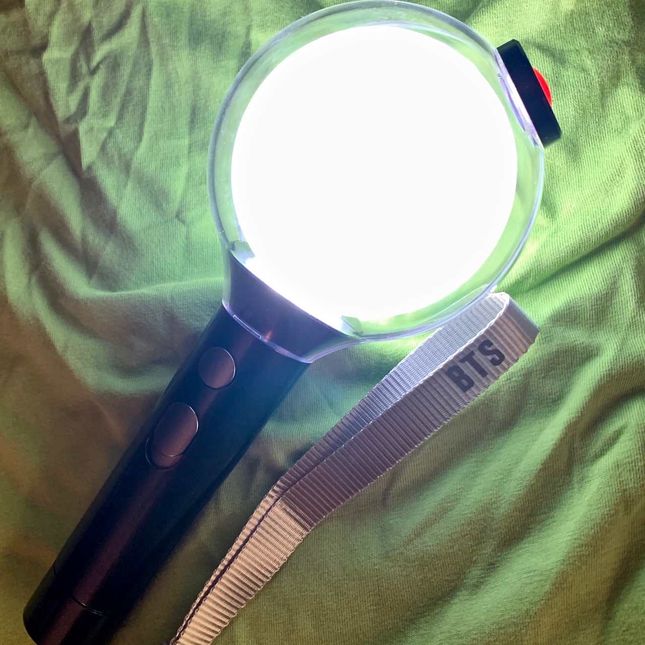
There was a discussion on the forum for the WLED firmware for controlling LED pixel strips about how the K-pop group BTS coordinates light-shows at its concerts using “Army Bombs.” Army Bombs are light-sticks that fans buy and take to concerts. They can be centrally controlled and used to put on huge stadium-wide light shows.

Someone in our house is a fan of BTS. They got an “army bomb” in preparation for a show in the US that ended up being cancelled due to COVID-19. I’m not allowed to disassemble it, but I was able to look at the label in the battery compartment and get the FCC ID and find their certification info.

For some reason the internal photos are embargoed until 10/11/2010, despite the thing being in the wild. However, the test report reveals that it uses…BLE, which I already knew. It doesn’t seem to have another radio, though. I did find internal photos for a similar device, registered in 2016, from the same manufacturer. The markings on the bluetooth SoC aren’t legible in the photos, unfortunately.

I can’t find any real teardowns, but one fan took hers apart. No closeups, but its clear there isn’t an IR receiver anywhere IR could be received.

The company that makes the Army Bomb is Fanlight.

Open Source and Hardware Engine Management Systems (ECUs)

I recently fell down a rabbit hole of car modding videos on YouTube. Most/all the videos I watch involve engine modifications, and there inevitably comes a time where the car gets a new tune on a Dyno in order to realize the potential afforded by the mods.

Tuning a modern car involves tweaking parameters in the engine management system, or engine control unity (ECU). Budget builds often make use of the OEM ECU that originally came with the engine (which may or may be the engine originally installed in the chassis) but the addition of forced induction via a turbo or supercharger to a normally aspirated engine usually calls for an aftermarket ECU.

Aftermarket ECUs offer another advantage for older vehicles; by using existing engine sensors, and perhaps adding a few more, a lot of engine control functions can be consolidated in the ECU, rendering various vacuum controls and mechanical linkages unnecessary. This can help clear space in a crowded engine bay, and also improve reliability, serviceability and, potentially performance, fuel economy and emissions.

From my research, tuning an OEM ECU may involve hundreds of dollars in software and hardware. A modern aftermarket unit suitable for upgrading a four cylinder engine starts at about $850, and one can spend more than twice that for an advanced feature set and the ability to run sequential ignition and fuel injection on a six or eight cylinder engine.

The prices of aftermarket ECUs aren’t outrageous compared to the cost of parts or labor for a big project, but they start looking more substantial if you plan to do most of the work yourself while scavenging parts as cheaply as possible. This got me wondering about whether there was a community of people either developing open source firmware for common OEM ECUs, or perhaps custom hardware.

It didn’t take too much looking to find two active projects with healthy communities around them, Speeduino and rusEFI.

Speeduino has been around since X. In 2017 it was a finalist for the hack a day prize. The author, Josh Stewart started out by using Arduino based hardware to run a lawnmower engine. By now it’s been used to run a variety of engines with 4-8 cylinders. The hardware is based on an Arduino Mega. It adds a robust automotive power supply, protection for the I/O channels and driver circuitry suitable for ignition coils, fuel injectors and other components.

A board capable of sequential fuel injection and ignition on 4 cylinder engines is available assembled for under $200. A unit that is plug-compatible with the ECU on a first generation Miata is available for ~$250, including an external housing.

Interestingly (to me), the Speeduino firmware takes advantage of the Arduino build environment and some libraries. This has enabled people to port the firmware to more capable ARM-based Arduino-like devices, like the Teensy. These ARM based platforms afford the possibility of more advanced peripherals, like CANbus controllers, more memory for data logging, and more headroom, allowing things like unlimited software timers to replace a limited number of hardware timers on the ATMEGA.

I think RusEFI has been around since, at least, 2013. There are already some great hardware options. $270 gets you a unit with a robust waterproof case and someone is gearing up to sell a board capable of running sequential ignition and fuel injection on a V-12 engine.

Both systems (currently?) rely on 3rd-party commercial software for the tuning process, but the software, Tuner Studio, is available for less than $100.

I could do a much longer post, but this post is long enough, so, this is where it ends.

CN3791 MPPT Solar Li-Ion Charger Module Hinky Circuit.

Last year, I paid about $3.66, with shipping, for this solar-powered MPPT lithium ion battery charging module on eBay to use with my small solar panels and scavenged 18650 batteries. It has some issues.

First off, the version I purchased/received is intended for 9v solar panels and I wanted to use it with a ~6v panel. This is set with a resistor divider. Careful study of photos from product listings showed that the divider was implemented using the same resistor value for the high segment of the divider, changing only the value of the lower segment’s resistor to change the setpoint.

The high segment had a value of 178KOhm and the low ranged from ~42KOhm for a 6v panel down to 12.6KOhm for an 18V panel. I didn’t have any SMD resistors of suitable value in my supplies, and I couldn’t find any I could scavenge on any surplus PCBs. I decided to use a trimpot instead. I had a variety on hand, and it would allow me to experiment on the optimal clamping voltage for the panel I had on hand, and an 18V panel I’d ordered. I chose a 200KOhm trim pot with the idea that approximating the total resistance of the existing divider would help preserve the stability of the control loop. If I were going to do it again, I’d probably choose a different configuration to minimize the impact of the pot’s temperature sensitivity. A simple choice would be ~20KOhm trimpot, configured as a variable resistor (short the wiper to one terminal) used it to replace the low segment, leaving the 178KOhm resistor in place.

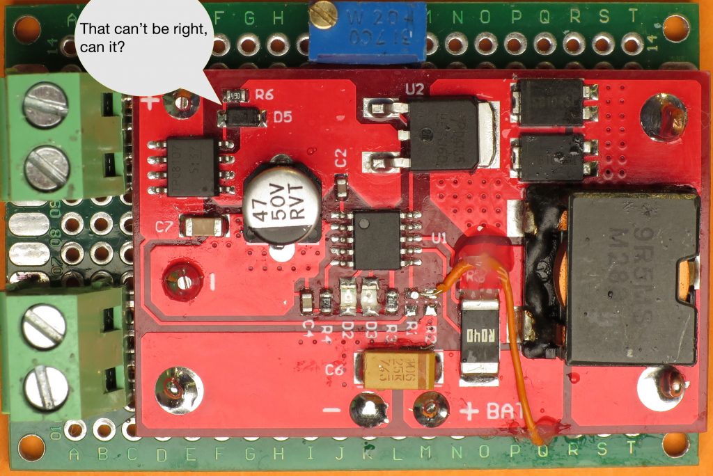
After adding the potentiometer, I connected the battery and panel and adjusted the potentiometer until I maximized the charging current. I was a little surprised by how low the panel voltage was, and so I started poking around. The first thing I checked was the voltage drop across a P-Channel MOSFET on the panel input. I was surprised to find that it was 500mV, though knowing that, I wasn’t surprised the IC was noticeably warm. The panel was dissipating 1/10th of the panel voltage over the MOSFET!

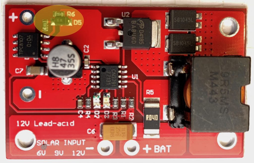
Some of the photos on some of the product listings showed a simpler circuit, without anything in the panel input current path. My guess is that the MOSFET and accompanying resistor and diode were added in a revision in order to protect the circuit in case the panel polarity was accidentally reversed, and/or to block leakage of charge from battery through panel at night. A schottky diode would accomplish the same thing more simply, but with a voltage drop of ~300mV. Properly implemented, a MOSFET based “ideal diode” would have an effective resistance of ≥ 50mOhm, and a voltage drop of ≥ 50mV at the ~1A max current my panel could deliver.

I’m not completely sure how the circuit was intended to work, but clearly, it wasn’t doing the job. I wondered if it would work properly if I was using the module with a 9V manual, as intended, but that didn’t seem possible, either. The panel + was connected to the MOSFET’s source, the rest of the circuit to the drain, and the gate was connected to the drain via a resistor and diode. By my reasoning:

  • that the gate would ≅the potential of the drain
  • the voltage drop from source to drain should be as close to 0V as possible in order to maintain the efficiency of the curcuit
  • therefore, Vgs would/should approximate 0V
  • but it won’t because the Vgs threshold for the MOSFET was ~2V!

I wasn’t sure how to fix the circuit, but I was sure that the gate needed to be pulled down to a lower voltage, so I cut the trace connecting the resistor the drain and connected it to ground instead. It worked well enough that the voltage drop over the input MOSFET went from 0.5V to a trivial number. I’m pretty sure though that I didn’t fix the protection function.

I’ve since received another version of the module which has revised the input circuit. The diode and parallel resistor connecting the gate and drain are still used, but there as another resistor which connects to the charging indication pin on the CN3791, and in so doing. This pin is open drain. When the battery is charging, it is pulled low, lighting the charge indicator LED AND pulling the input MOSFET gate low. Vgs ≅ -Vpanel ≅ Vs ≅-6V, turning the MOSFET fully on.

Thinking through this further… if the battery is charged and the panel is illuminated the gate will approximate the potential of the input MOSFET drain and, since the only load on the panel is the quiescent current of the module, then Vsd ≅ 0V ≅ Vgs and so the MOSFET will be off, save any current through the body diode.

If the panel is dark and the battery is charged then Vd of the input MOSFET will, at most, be at battery voltage (Vbatt), Vs will be ~0v, Vg will ≅ Vd, Vgs ≅ Vd and the input MOSFET will be off.

If the panel is reversed Vs will be below GND and well below Vg ≅ Vd ≅ Vbatt so Vgs will be Vbatt + Vpanel, and the MOSFET will be off. Note: This means that reverse polarity with an ~18V nominal panel would exceed the Vgs maximum of 20V for the TPC8107 MOSFET used at the input.

If I get around to it I’ll draw a schematic and add it to this post.

Balight 21W Folding Solar Panel USB Charger Partial Teardown

I picked up a 21W, 3-panel Balight folding solar panel-based USB charger from Amazon for ~$36 a couple of weeks back. It uses high-efficiency SunPower Maxeon cells much like similar 20-21W panels from AukeyAnker and dozens of obscure brands. All of them have the same basic construction. They are all made from nylon ballistic cloth. Each fold has a panel made from two SunPower cells encapsulated in a flexible waterpoof sheet. The panels provide power via two 5v USB ports, which presumably have some sort of voltage regulator.

I wanted to know more about how the chargers worked. In particular, I wanted to know if they were wired in series, or parallel because I wondered if it was worth trying to tap into the raw output, before the USB regulator to reduce power conversion and resistive losses for some applications.

I thought I’d be able to get the information I needed by finding someone documenting a teardown of their own panel on YouTube or a blog post. Despite the dozens of variants from dozens of brands and a handful of manufactures though, I didn’t find what I was looking for.

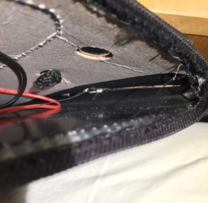
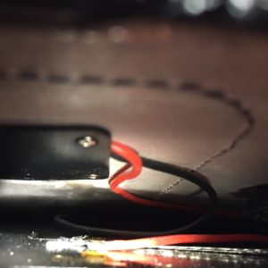
So, I decided to dig up a seam ripper and open my panel far enough to get a look at the wiring, and tap in to it upstream of the voltage regulator.

The panels appear to be wired together with some sort of woven wire conductor. I had some hope that all the cells would be wired in series, to give a nominal panel voltage of 18v. Based on what I could see, and measuring the voltage before the regulator in full sun, it looks like each panel is wired in series, for 6v nominal voltage, and then the panels are wired together in parallel. I was disappointed at first, but this arrangement makes sense in upon further thought.

Using a 2s3p configuration means that the input voltage into the switching regulator should be pretty close to the 5v (actually, 5.2v with enough sun and a light enough load) output of the USB power regulator, which will typically have higher conversion efficiency than 12 or 18 volts. It also means that the manufacturers can stock one converter for everything from a 7W single-panel charger, up to a 28w 4 panel charger without the converter having to support a wide range of input voltages. Perhaps most importantly, it means that partial shading of one panel shouldn’t have a disproportionate impact on the power output of the entire array.

The only downside is that resistive losses in the cabling will be higher with lower voltage and higher current, but that the interconnects aren’t more than a foot or so, the resistive losses shouldn’t be too high.

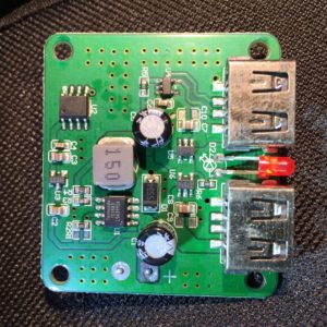
As for the converter itself, I may look at it more closely and add some more details, but, a few initial observations:

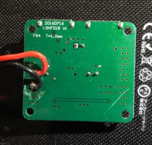
  • The PCB design has extensive ground planes on top and bottom, tied together with vias.
  • Both outputs are served from a single buck-converter (step-down) power supply based on a Techcode TD1583, which is a 380 KHz fixed frequency monolithic step down switch mode regulator with a built in internal Power MOSFET.
  • It looks like only port 1, at the top right in my photo, has the data lines connected, which suggests that it is the only one with fast-charge coding.
  • IC U2 looks like it has its markings sanded off. I notice though that one of its pins is connected to the enable pin on the TD1583, leading me to think that it is responsible for cycling the output to make sure devices draw as much power as possible when the panel voltage rises again after clouds or an object reducing the light falling on the array pass. I don’t know if it is a MCU, some sort of timer, or comparator, or what, though.

There you go. I can’t be sure that other folding solar arrays like this one are wired in the same way, but if they only support a 5v output, I suspect they will be. I hope this proves useful to someone besides me.

New to Me: EDC 521 DC Voltage/Current Source

Last week I came across a miscategorized eBay listing for an Electronic Development Corp (EDC, now owned by Krohn-Hite) 521 DC Voltage/Current Source. It was listed in the network equipment section, with “Juniper” as the manufacturer.

The EDC 521 is a precision DC reference source with high accuracy, precision and stability, for the calibration of meters and sensors. It can output voltage in three ranges, (0-100mv, 0-10v, and 0-100v), and constant current in two ranges, 10mA and 100mA (with compliance voltages up to 100V). In each range, the precision/resolution of adjustment is 1ppm. Overall stability in Voltage mode, within the devices operating temperature range is 7.5ppm over 8 hours, 10ppm over 24 hours, 15ppm over 90 days, and 20ppm over a year. The temperature coefficient (which is included in the above estimates). It is microprocessor controlled and has a GPIB interface to allow remote control.

To achieve its basic stability, it uses an aged and selected 1N829 temperature compensated Zener diode as its primary voltage reference. This diode is driven by a stable precision current source at a current chosen to provide the best combination of temperature stability, long-term drift and low-noise for the individual diode used in each unit. Adjustments are made using a custom, precision 24-bit digital to analog converter.
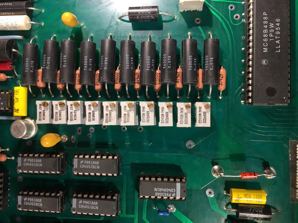
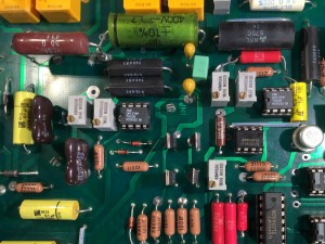
Voltage divider resistors and 1N829a temperature compensated zener voltage reference.

The DAC works by feeding the reference voltage across a resistor divider to obtain 10 output voltages, tapped at 500mV intervals. If I understand correctly, these voltages are switched to provide analog voltages for each decade, these voltages are buffered, then then weighted and summed using some precision resistors before being fed to the output amplifier.

When the package arrived yesterday, I saw why the listing had been miscategorized — it was packed in a box for a Juniper Networks switch. That, and the sticker noting a failed calibration attempt in 2009 makes me doubt the seller’s assertion that it was “pulled from a working environment.” Not that I expected a pristine, calibrated instrument for $150.
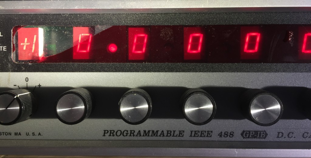
IMG_8649

Inside the box, I found things in a bit worse physical shape than I expected. What I thought was shadow/glare in the photo from the ebay listing, was actually a torn red filter over the LED display. And the underside of the case, which wasn’t pictured in the listing, had a huge dent.
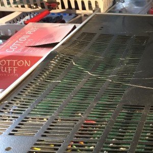
IMG_8625IMG_8643

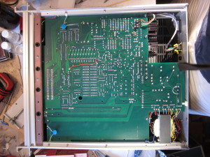
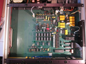
On closer inspection, the dent didn’t reach the PCB inside, and I was able to remove the panel and hammer it out. Once inside, I found that everything had a fine coating of persistent dust. Hitting it with canned air shook some of it loose, but most of it remained.

So, I got to work rinsing it with a lot of isopropyl alcohol which I then chased off the edge of the board with canned air. After a few repetitions, the top and bottom side of the board were pretty clean. I then looked over both sides of the board closely, looking for damaged components, and cleaning out little pockets of residue.

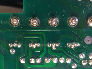
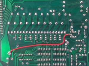
I didn’t see any damaged components, but along the way noticed signs that the board had received some major revisions. There was an obvious bodge wire on the bottom of the PCB, but it was also clear that new holes had been drilled to receive additional components. On the top side, I found a cut trace, along with a couple of added resistors and a couple of capacitors. I haven’t traced everything out, but its obvious that the bodge wire connects to one end of the internal reference divider, and the rest of it is on the opposite end, so it would seem likely that its helping isolate the reference divider, and the voltages it produces, from noise sources.

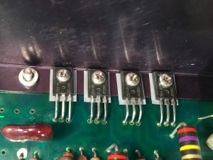
It also appears that a number of power transistors have been replaced. Unfortunately, none of the components in question have obvious date codes, so its hard to guess when the modifications were done, and whether the transistors and the filters were added at the same time. Perhaps one of you knows how to decode the markings?  First line is a Motorola logo followed by “616,” the next line is “JE350,” which is the model/part number. The datecodes on other components pretty much all date to late 1996, and the MPU board has a label with the firmware revision and is dated January 1997.

Before closing it up, I took care of the loose plastic supports for the back-edge of the PCB, which holds heavy electrolytic filter caps for the power supply. I cleaned the old, crusty, failed double-sided foam tape off and replaced it with new tape so I could stick the supports to the back of the chassis again.

I powered it up, and gave it a quick check on all the voltage and current ranges. It seems pretty close to its 1 year tolerances. I was surprised by the amount of time it took to warm up and stabilize, but when I checked the manual, I saw that the warm up time is speced at 2 hours.
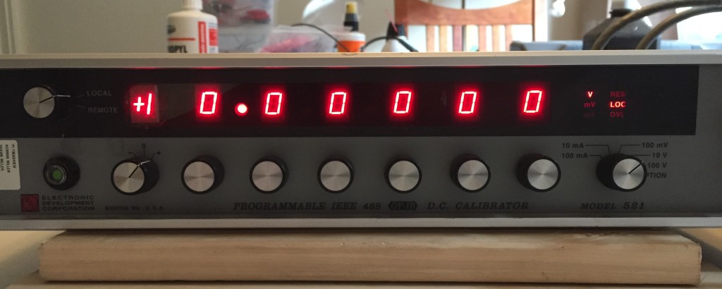
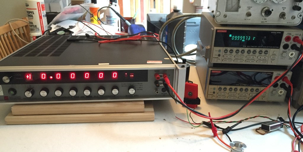
IMG_8648 IMG_8647

I powered it down over night. This morning I set up my computer to voltage readings ever few seconds and then powered it back up. I’ll post a graph once I have a days worth of data. After that, I’m going to write a script to run through all the possible settings and log the measurements. So, more to come!
A Trip to the Museum of Communications

This morning, I woke up with an itch, an itch to see a switch.

Version 2

No, not that kind of switch, something bigger!

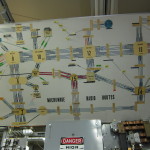
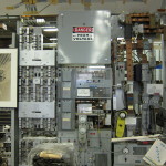
Battery Reserve Switch

Nah, that’s not a switch…

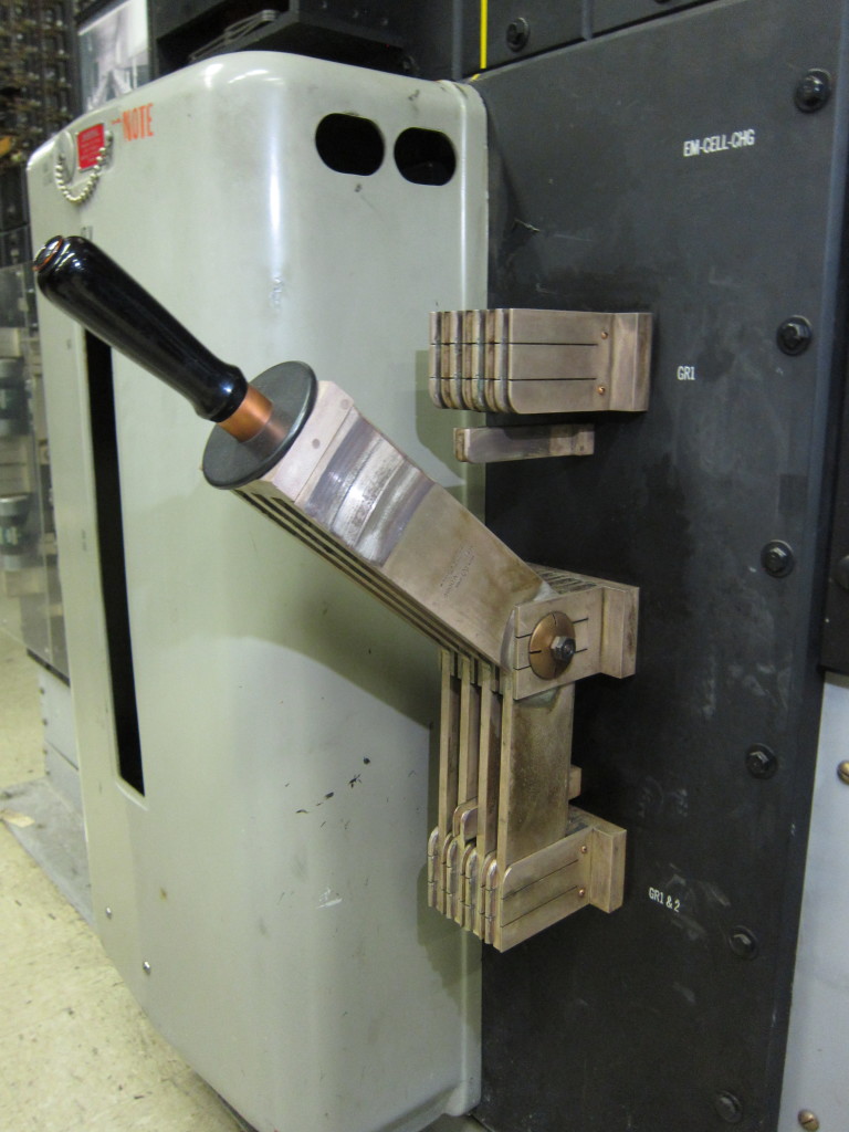
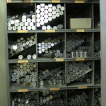
Panel Switch

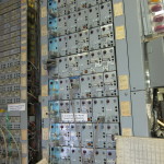
That’s a switch! Well, part of one.

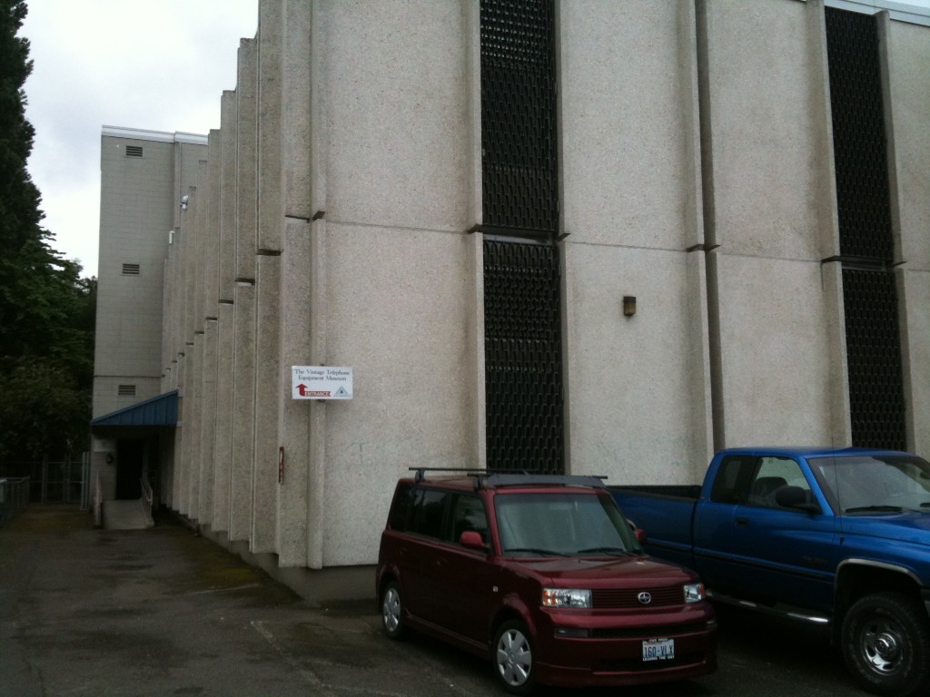
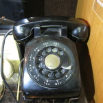
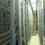
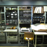
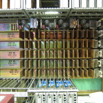
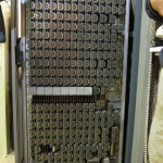
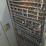
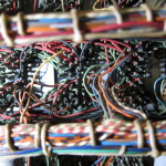
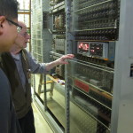
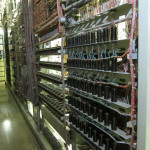
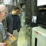
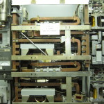
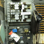
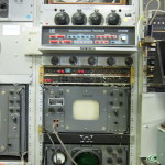
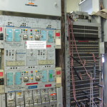
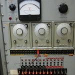
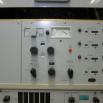
Museum of CommunicationsIt is part of a panel telephone switch, one of a number of operational telephone switches at The Herbert H Warrick Jr. Museum of Communications, a little known technological treasure trove in the Georgetown neighborhood of Seattle. The museum fills the top two floors of a Century Link central office building.
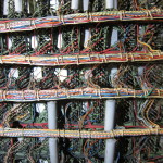
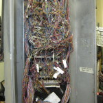
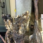
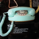
The museum’s collection includes all manner of equipment and memorabilia from over a century of telephone history. The presentation of the collection is a bit uneven. There are carefully dated and labeled exhibits of phones and other equipment, along with display cases stuffed with lineman’s tools, but to me, that’s all secondary.
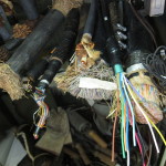
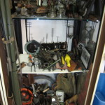
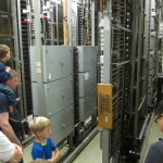
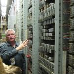
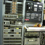
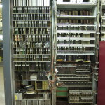
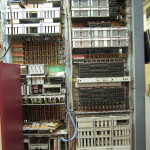
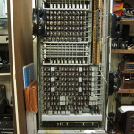
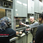
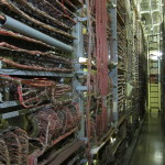
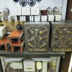
The best part of the museum is that it houses multiple generations of telephone exchange switching equipment, the sort of stuff that used to fill small buildings and connect thousands of homes to the telephone network. Much of it of it is operational, and interconnected, and attended by a staff of volunteers, many of them technicians and engineers retired after long careers with Ma Bell and her successors. They answer questions, give tours, and maintain the equipment.

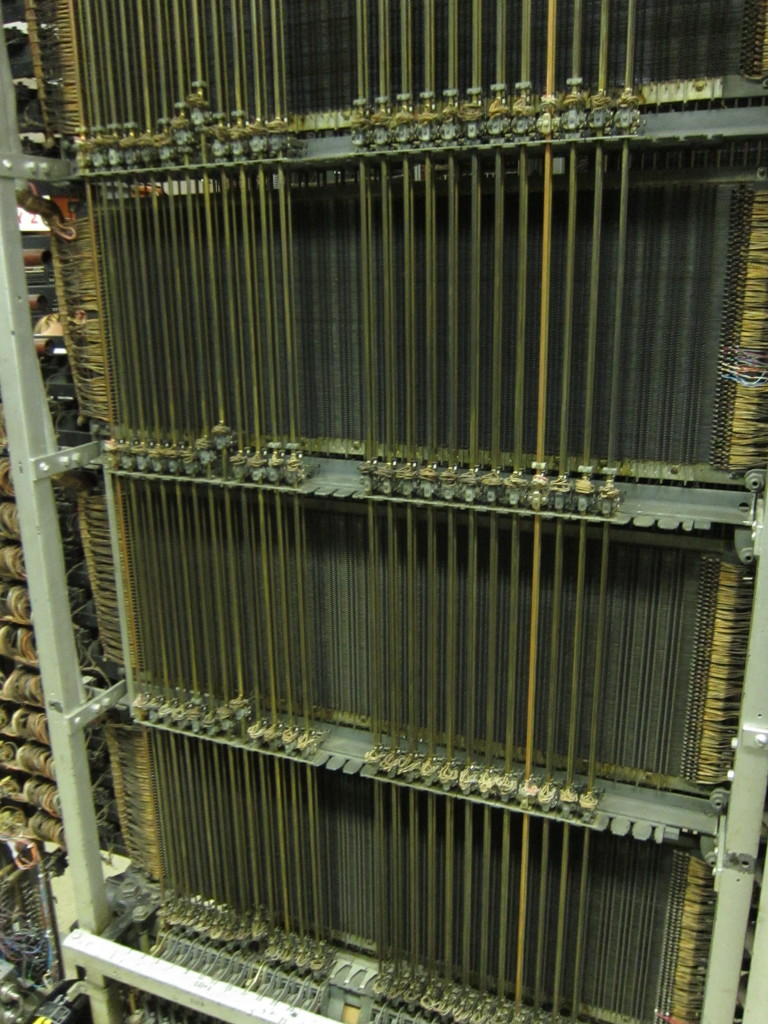
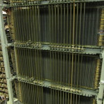
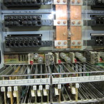
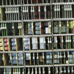
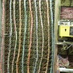
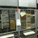
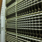
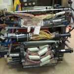
The automatic switching equipment spans almost a century. The oldest automatic switch is a panel switch that served the Rainier Valley. It was installed in the 1920s and served for over 50 years. Unlike that later automatic switches in the museum, which were made in a factory and then installed, the panel switch was assembled on site at the central office and moving it five decades required removing walls. They also have a #1 Crossbar Switch (#1XB) from the 1930s, and a #5 Crossbar (#5XB) from the 1950s. The panel and crossbar switches are all operational. Calls can be placed between lines serviced by the switches and you can hear the progress of the call set-up and tear-down sound across the racks as the various electromechanical parts do their thing. They also have a number of operational PBX systems, some old-time switchboards, some small Strowger step-by-step switches and a not yet operational #3ESS, a small variant of the first switches using transistorized logic for control.

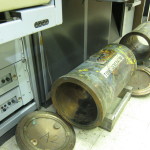
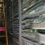
The collection also includes inside plant, like power distribution equipment, outside plant, like cables, along with a variety of trunking and long-distance equipment, including equipment for carrying national network television broadcasts.

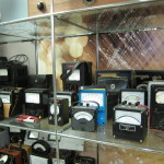
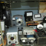
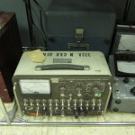
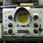
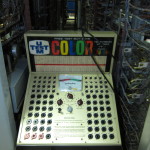
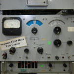
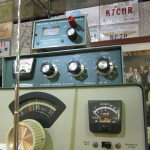
There is also test equipment spanning decades, and a nice cache of HAM radio equipment.

The museum was originally called the Vintage Telephone Equipment Museum when it was created in 1986 by Herbert H. Warrick Jr. Warrick was an engineering director at Pacific Northwest Bell, and started the museum with the company’s support to preserve generations of vintage telephone equipment that was being phased out in the transition to digital switching and transmission. More recently, it became affiliated with the Telecomunications History Group.

I’ve made many visits to the over the years, and each time, I learn something new. I recommend it to anyone with an affinity for technology, particularly communications and computing, but it should also interest anyone curious about industrial and economic history. I hope I’ve whetted your appetite.


HP 6177C DC Current Source Troubleshooting/Repair

I picked up a Hewlett Packard 6177C DC Current Source on ebay for less than $75 shipped. This is a precision constant-current source that can deliver 0-500mA at up to 50V.

IMG_7318The seller described the unit as used with responsive controls and indicators. When I received it, I could see that while in generally good physical shape the upper right portion of the front panel was more bent/buckled than I could make out in the eBay photos.

So, first thing I did was partially disassemble the unit to fix the front panel.

Once I got it back together, I did some quick functional tests and found that the current output was consistently 1/10th the expected value. In the 500mA range with the current pot set to maximum, it produces a max of 53mA of current, on the 50mA range, it produces 5.3mA, and on the 5mA range, 0.53mA. This behavior doesn’t vary noticeably between shorting the outputs and having a 30 Ohm load. With a suitably high resistance, the voltage will hit >50v, provided the current doesn’t exceed ~50mA.

So, next step was to look at the service manual and work through the troubleshooting steps.

First thing is to check some voltage rails.  These all checked out, though a few were out of spec on ripple.

Next is to go through the problem isolation procedure, which starts with checking the guard voltage to see if it varies between 0 and -1V. Nope! In each range it maxes out at… ~100mV, or 1/10th of the expected value. Notice a pattern forming?

I started to work through the guard supply troubleshooting instructions, but I got hung up. After disabling the main supply, as instructed and checking a few voltages, it wasn’t clear to me whether I should go immediately through the subsequent steps, or reverse the change and proceed from there. Subsequent instructions just raised more questions.

I asked for guidance in the EEVBlog forum, and while waiting for a response, worked to better acquaint myself with the schematic and theory of operation of the device.

I’m still not sure what to do, and rather than pushing forward, I realize that I already have other incomplete projects that need my attention, I’ve gathered everything up into a bin and put this one on the shelf, for now.