I’ve passed up a few chances to get a Keithley 2001 7.5-digit multimeter on eBay for ~$500, because while that’s a pretty good deal for a Keithley 2001 in working order, it’s more than I can justify spending on a 7.5 digit multimeter that I want, but don’t need. Somehow though in my twisted psychology, spending $300 on a two-decade older 7.5-digit multimeter with known issues is perfectly acceptable, because I recently did just that.
A couple of weeks ago, I was checking eBay on my phone while waiting for an appointment and came across a new llisting for a Datron 1081 Multimeter that caught my eye. It was listed for parts or repair for $300, or best offer.
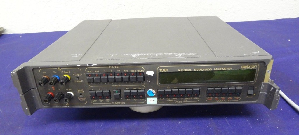
According to the description, it had been damaged in shipping, and gave an error during selftest. From the photos, it looked like the shipping damage was confined to a broken “ear” on the front of the case, and misalignment of the front panel. Definitely interesting…
Some quick googling confirmed that the 1081 was, as I thought, a 7.5-digit capable multimeter with high stability and and the ability to use an external voltage reference. I thought it would be useful for evaluating and calibrating precision voltage references, and 6.5-digit DMMs, like the Keithley 2000 and HP/Agilent/Keysight 34401a. I couldn’t find an operators manual for the 1081, but I hoped the 1071 manual I found was correct that the selftest error was with the AC measurement circuitry. I’m mainly interested in DC, so I wasn’t too concerned.
I reviewed past eBay listings on my phone to confirm that the 1081 typically goes for more than $300, checked my gut, and decided to make an offer of $200.
The seller responded within a few hours that the listing had generated a lot of interest, and counteroffered for $275. At this point, I was back home, with the ability to browse eBay without the limits of a phone. I should have taken advantage of this to investigate past listing a little more thoroughly. If I had I would have realized that some of the higher sales prices weren’t actually sales, they were expired listings that eBay wasn’t filtering properly. I didn’t though, instead I accepted the offer.


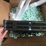
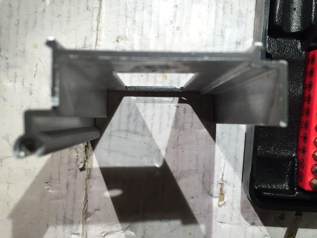
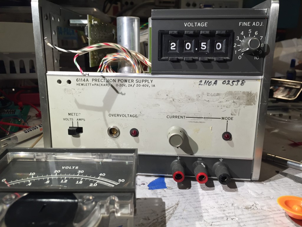
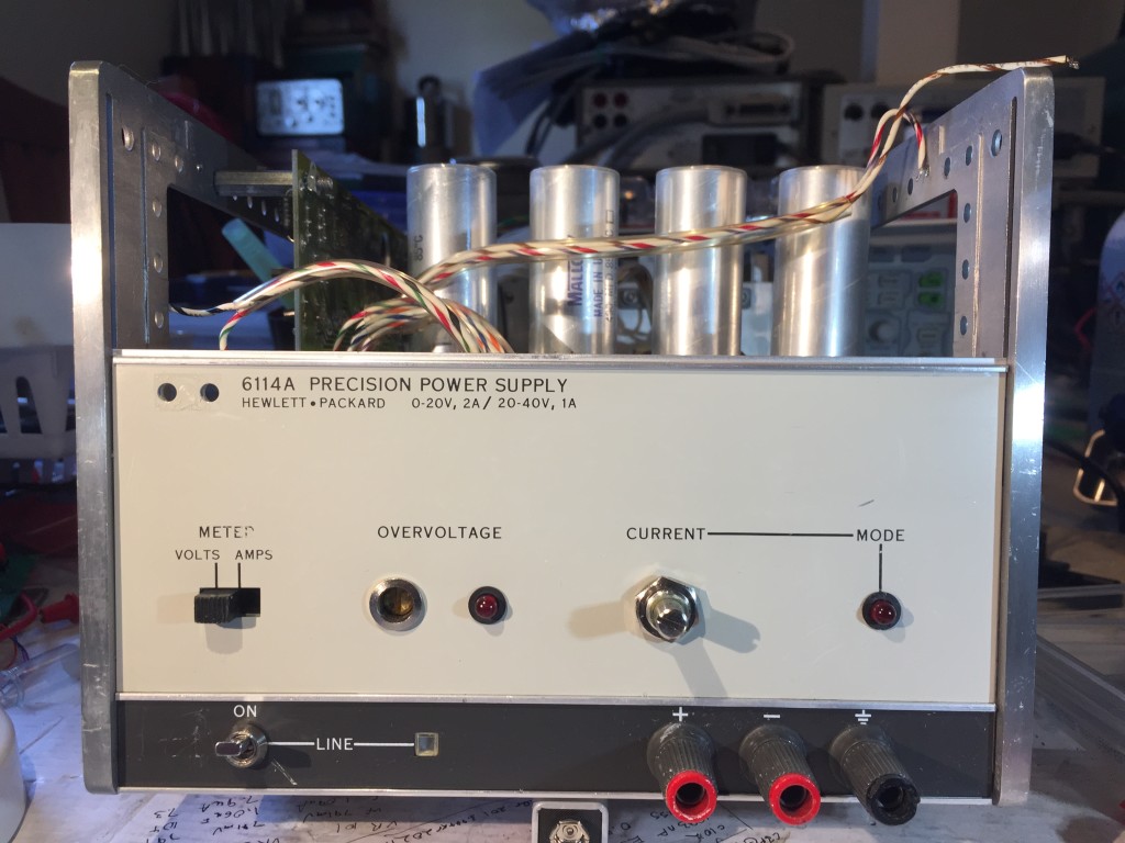
It took a few days for the seller to ship the item, and it was shipped by FedEx Ground, so it took over a week to get to me. It arrived last Friday, packed well in a Cisco router box with reused foam endpieces and packing peanuts for extra protection. It was in the physical condition I expected; the case damage was limited to an extremity, and the main enclosure was sound. I opened it up for inspection and to deal with the misaligned front panel.
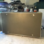
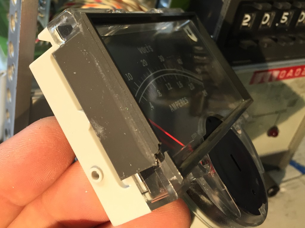
The front panel is a metal plate covered with a big printed plastic sticker. The sticker holds a smoked plastic protective lens over the display. The sticker was loose at a few spots, including the protective lens, which allowed dust and exposure to further weaken the adhesive. I decided to remove it, clean it up, and reattach it.
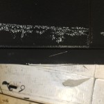
I heated the panel with a hair dryer to loosen the adhesive, but that didn’t work all that well. I ended up peeling the outer layer and printed layers of the sticker off its backing. Some adhesive remained on on the printed surface of the label, and the backing remained stuck firmly to the metal plate. I used a plastic scraper to remove most of the backing, but getting the rest off required a razor blade, elbow grease, and solvents (“Goo Gone” worked best). I used isopropyl alcohol to clean the remaining adhesive off the back of the printed sheet. Unfortunately I think the process of peeling off the label led to some of the printed brown background along the left side of the lower edge crazing and flaking off. I considered trying to apply a new background of spray paint, but decided the risk of causing further damage wasn’t worthwhile.
Once I got everything cleaned up, I decided to use some non-corrosive silicone adhesive to stick everything back down again. I smeared a thin layer all over the back of the sticker, and around the edge of the smoked lens before lining everything up and sticking it back down, smoothing it out and wiping off any ooze. I weighted the area over the lens and let it cure for a few hours before reattaching it.
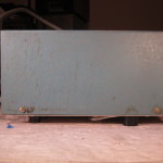
-
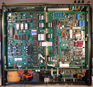
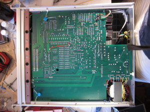
- Top
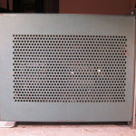
-
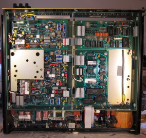
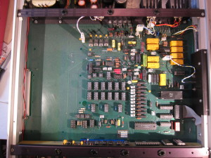
- Bottom
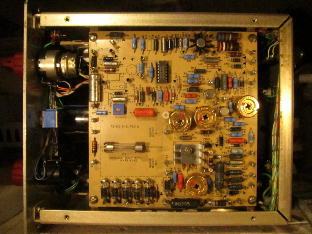
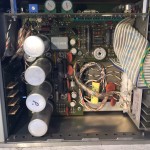
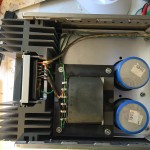
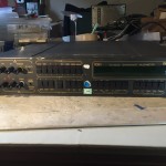
As for the electronics, there sure are a lot of them, and very few of them are electrolytic capacitors – the component most apt to fail on older equipment. I looked everything over very closely.
I was relieved not to spot any physical problems, because while everything is through-hole components, many of them are packed in very closely, and a number of them look like nothing I’ve ever seen before. Repair would be challenging.
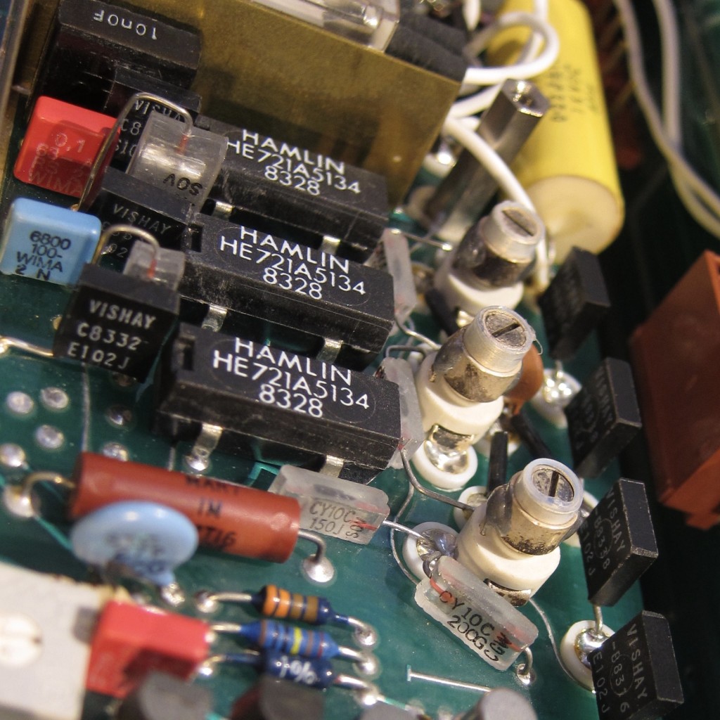
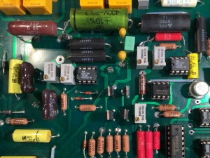
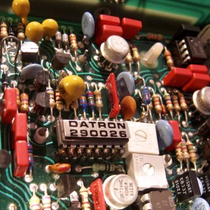
My first Glass Capacitors
Actually, there was one problem, but one I expected to find.
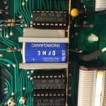
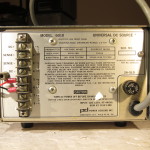
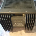
The back panel was labeled at manufacture with a battery replacement date of April 1992! Either the battery hadn’t been changed, or whoever did so was too lazy to update the label. Inside I found the truth, the battery had a datecode of 1984, like most of the other components. Fortunately it still had a voltage of 3.7v, but I’ll be changing it soon.
I found a few other interesting things as I looked the device over.
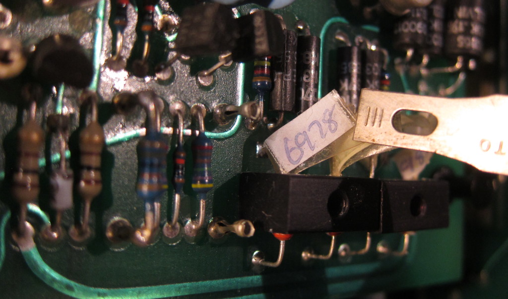
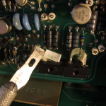
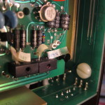
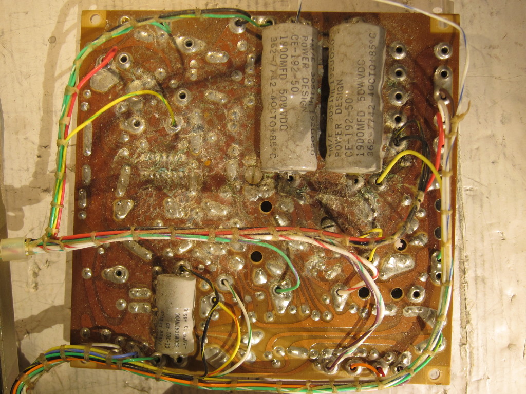
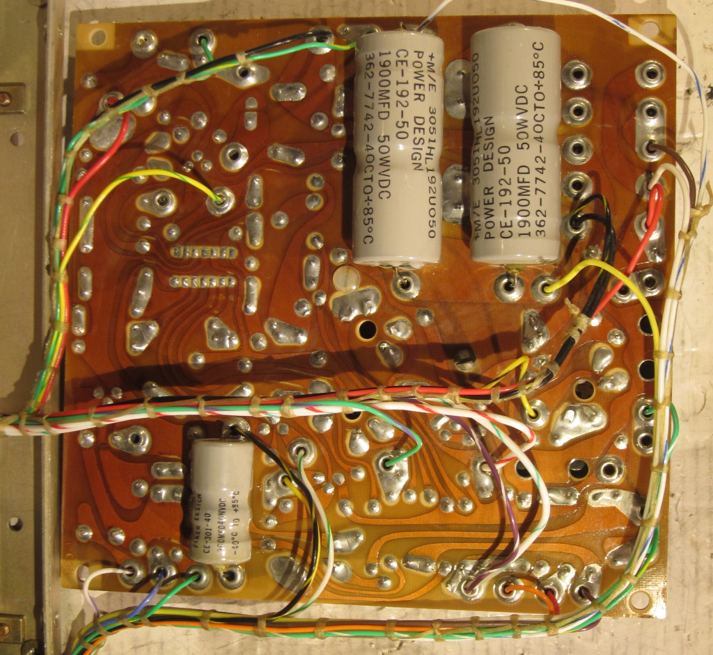
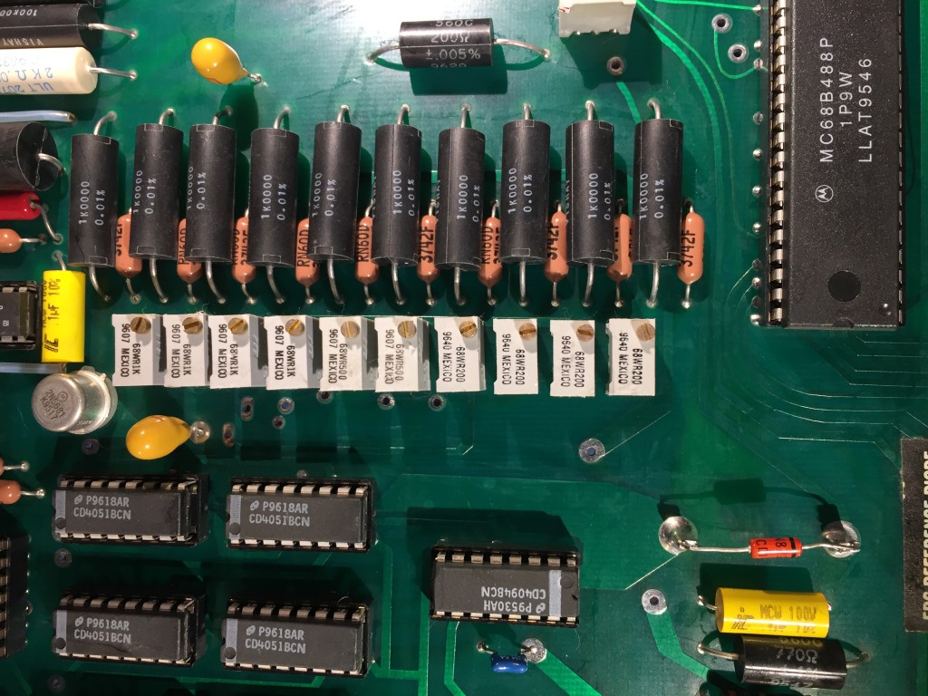
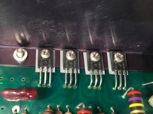
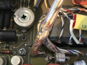
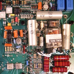
The photos above feature four 1N829a temperature compensated zener diodes. Together, they make up the heart of the voltage reference. They are each numbered with a unique serial number because they were carefully aged for months (or years), then characterized for noise, stability, voltage, and the current at which they have flat temperature sensitivity. My understanding is that the four Zener are connected as two parallel series of two.
I plan to look at these in more detail in a future post, because the unique characteristics of this voltage reference may make it the most notable part of this device. The use of hand-selected temperature compensated Zener was a common practice in a variety of precision instruments at one time, even so, the use of multiple TC Zeners was unusual, as is the stability they obtained. Also by the mid-1980s, when this device was made, use of temperature stabilized burried-Zener voltage references, like the LM199 (introduced in 1976) was commonplace.
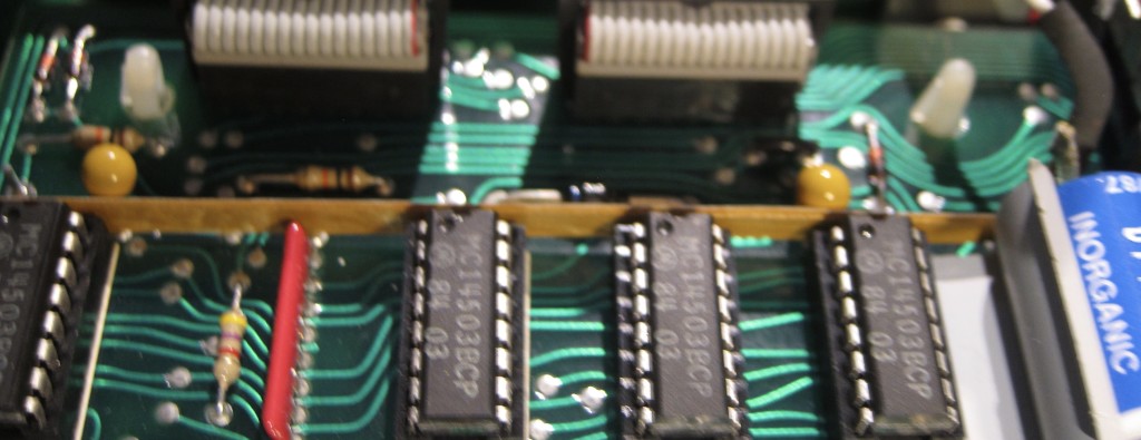
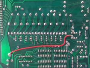
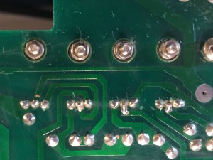
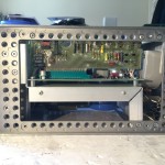
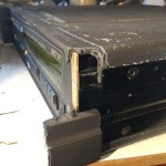
This insulated metal strip running the length of the digital board between a row of I/O bufferes, and the ribbon connectors, also caught my eye.
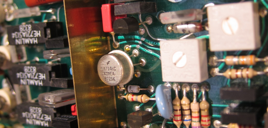
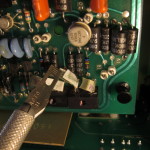
I found evidence of a component level repair on the AC RMS converter board. Most of the components on the AC RMS converter board, and most of the other boards, have date codes no later than mid-1984, but the Fairchild opamp in the hermetically sealed package in the photo above is dated from 1987. The GPIB board seems to date from 1985, and there are some socketed ICs on another board that have 1986 date codes, while other chips on the board are from 1982 or 1983.

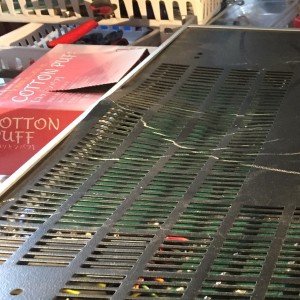
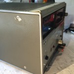
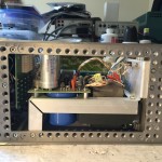
Artifacts of repair can also be found on the inside of the case, where some of the melted nubs holding the RF shielding seem to have sheered off and been replaced with some glue.
Functional Tests
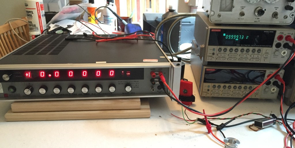
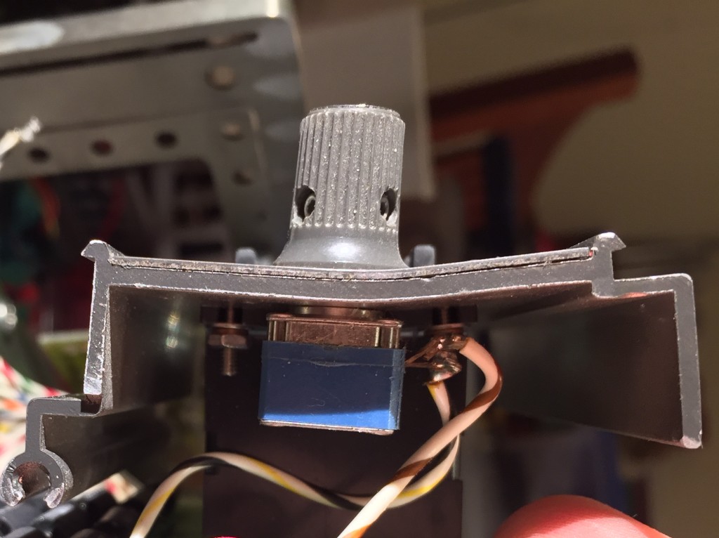
After checking it over and fixing the front panel, I reassembled it, and powered it up. On the EEVBlog forum, “dacman” suggested that self-test error could simply be the result of running the tests with the “guard” switch was set to remote. I could see from the photos on the listing that it was, indeed, set to remote, and it still was when I received it, so I set it to local guard and ran the self tests. Everything passed!
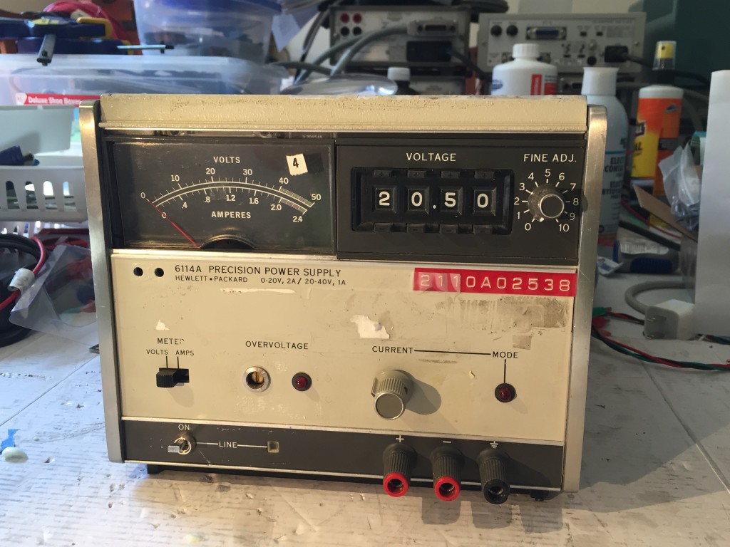
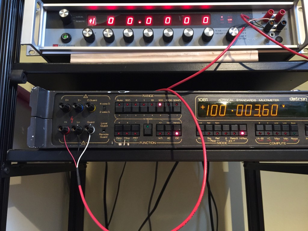
After that, I did spot checks on the 100mv, 1v, 10v and 100v DC ranges using the output from my EDC 521 DC voltage calibrator. The EDC hasn’t been calibrated in years, though from my tests, it is accurate to within the combined 1year tolerances of both it and all my 6.5 digit DMMs. The readings are stable over the short term.
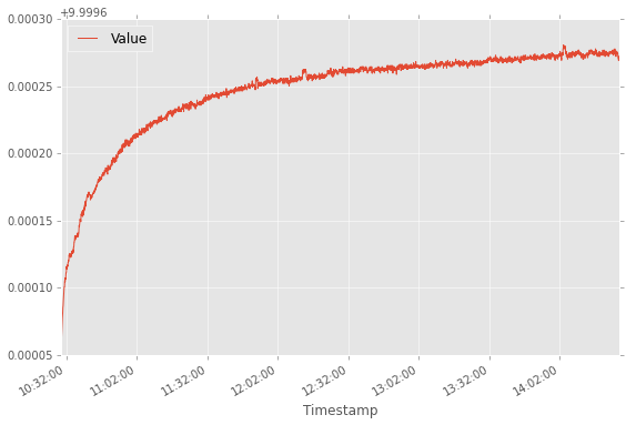
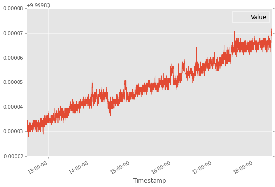
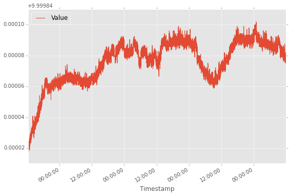
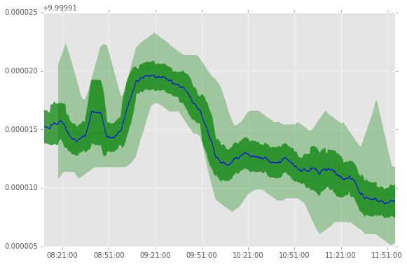
I’ve also done some longer term checks of a 10v signal over a period of days and found that for the most part, the peak-to-peak variation is within the 20-40uV range measured by one of my Keithley 2700s (it is a 6.5-digit meter, but in stats mode it collects and calculates 7.5-digit values) in my Seattle home, near an external wall, without any heating. Sometimes the Datron has reported a wider range than the Keithley, sometimes a narrower range. I’ll need to get logging working over GPIB soon so I can can look more closely at the trends.
Unexpected behavior
In the first few days, of use, I ran into a few instances of unexpected behavior, some of which may have been user error, some of which may have been software bugs, and some of which is as of yet unexplained.
One of the first things to crop up happened while I was checking the 100v range with a 100v output. After the initial readings seemed good, I left it for a while and checked it while I worked. About 15-30 minutes in, I looked over, and it was reporting values of 110v or more, and they were changing quickly. I haven’t been using the EDC much in its 100v range, so I breifly considered the possibility that it was at fault, but a quick look at the Keithley 2700 measuring the same source showed that the voltage was still stable at 100v.
The reading on the Datron was still on the move and soon it was reporting an “Overload.” I tried changing to the 1000v range, but the Overload message remained. I cut the EDCs output and after about 30s, the Datron cleared the overload message and started giving readings again. I applied an input again (I can’t remember if it was 10v or 100v), and it again gave plausible readings. I left it for a while and continued checking it, and after a while, it was again reporting an overload. This time cutting the EDCs output didn’t clear the overload message, and I ended up power cycling it.
Since then, I’ve been focused on the 10v range, and I haven’t seen this behavior again. I have had it with a 100v input for the last 18 hours or so though, and its been solid. I’m beginning to suspect that the problem may have been the result of user error. At some point, I think I’d used a function that “zeros” the meter. I thought this worked like the relative measurement option on my Keithleys, which can give readings relative to any voltage. The Datron 1081’s feature is different. The zero-point is supposed to be set with the inputs shorted, and the value is stored and used until the next time the meter is zeroed. If it is more than a small portion of the full range (1% or so), it will give a overange error. I’m wondering if perhaps the zero-point that I or someone else previously set was near the limit, and perhaps some internal auto-correction ended up pushing things over the limit. This is just a stupid wild ass guess though. All I can be sure of is that since setting the zero point for all the ranges with the input shorted, I haven’t had this happen again.
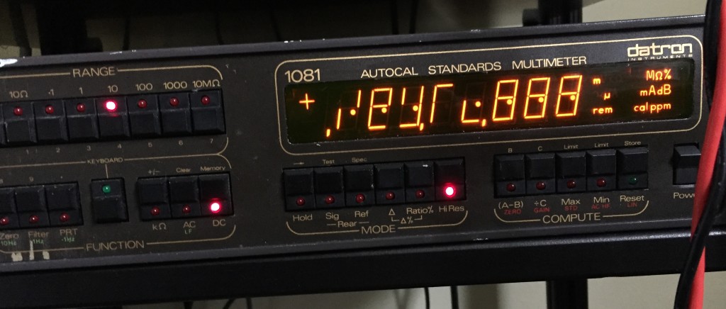
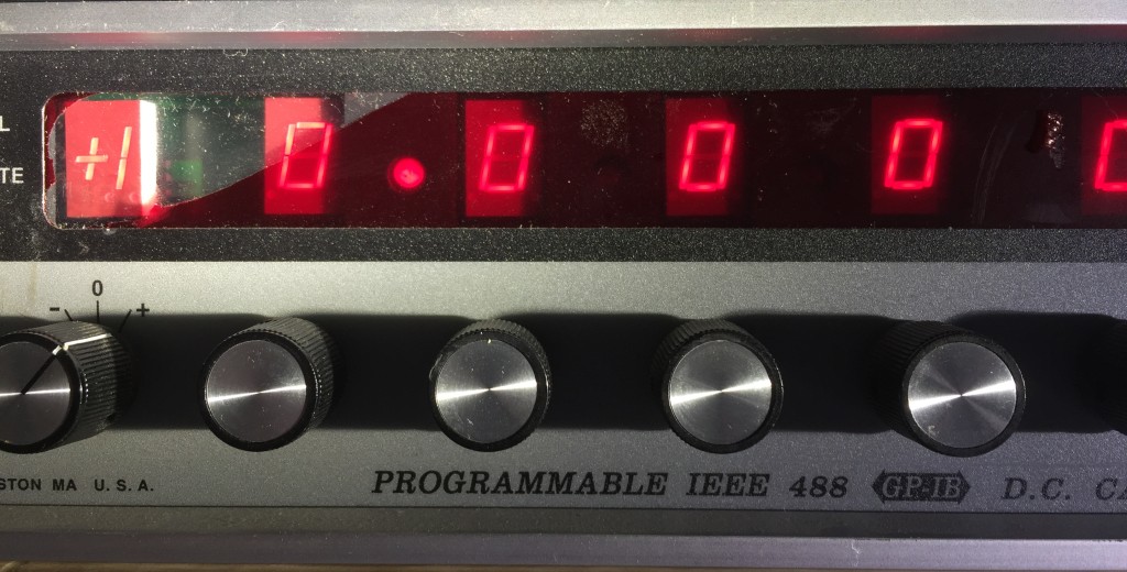
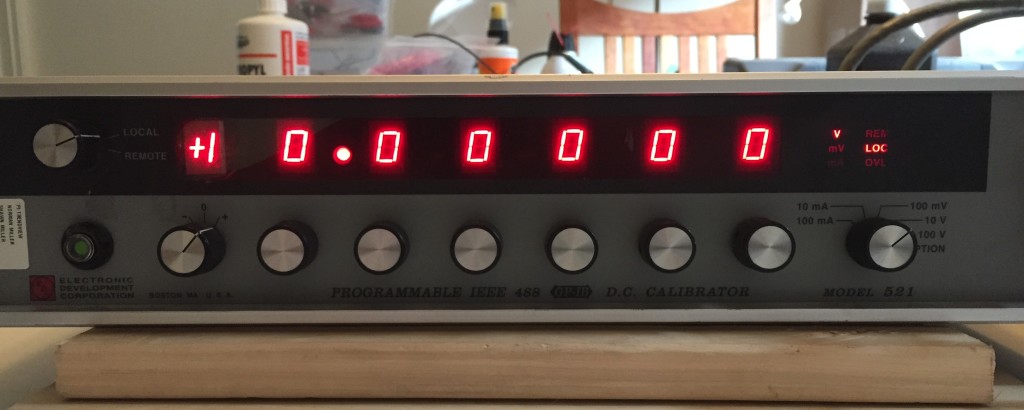
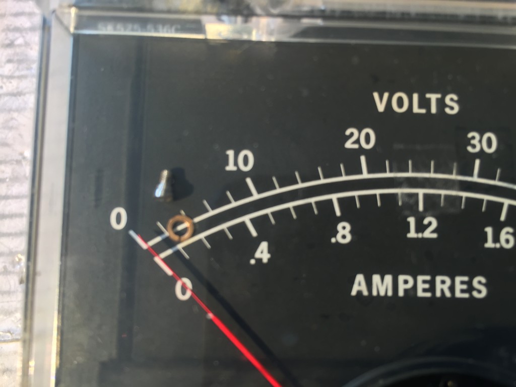
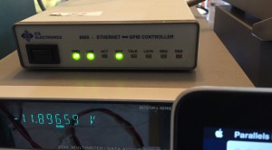
I spotted the next problem after leaving the DMM on overnight. When I checked it the next morning, I suspected that the display had frozen because the last digit didn’t change once. I pushed a button to change the value displayed, and was treated to the above, after a minute or two, it seemed to reset itself and resume operation.
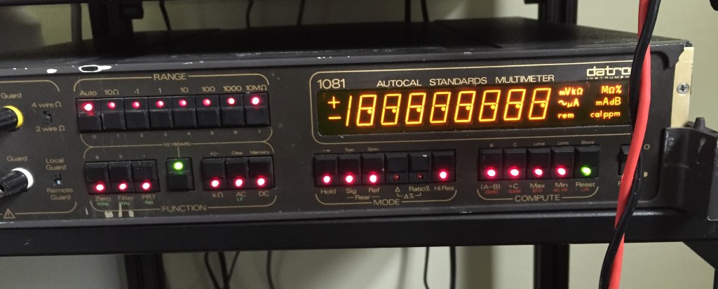
The next morning, after leaving it overnight, I again found it with a frozen display. The first button I hit produced a similar result to the previous day. I tried hitting another button (I don’t remember which) and the rest of the display segments and all the indicator LEDs on the buttons lit up too. This time, it didn’t reset itself, at least not before I got tired of waiting.
I haven’t seen this behavior since, despite leaving the unit on continuously. A few days ago though, I decided to investigate a hunch. I thought that that when I saw this problem behavior previously, I may have left the unit displaying the delta between minimum and maximum values. So, I again left it in that state, and the next morning, the display was again frozen. This suggested that my memory was correct, and that it was infact a software problem. However, the following morning, after again leaving the unit in min-max display overnight, the problem didn’t present itself. So, it seems that I still don’t have it figured out.
What Next
I’m trying to decide where to go from here.
At the very least, I’m going to power it down, open it up again, and take a close look at power supply voltages and ripple.
When I power it up again, I’ll keep an eye out for a recurrence of any of the bad behavior I observed. If so, it will suggest that some of the problems are the result of bad solder joints that act up when the unit is coming to a new thermal equilibrium.
Beyond that, i’ll do some logging over the GPIB interface to get a better sense of stability and tempco. I also need to investigate the resistance and ACV functions.
After that, I’ll have to consider whether to get it calibrated, or figure out a way to calibrate it myself. I’d also like to investigate its ability to use an external voltage reference to provide high-precision comparisons between different voltage standards. Doing so will require either figuring out a source of the (likely expensive) low-thermal-EMF rear panel connectors, or replacing them with similar performance and lower cost.
I’m also still looking for a Datron 1081/1082 Users Handbook (the 1082 is basically a 1081 with all the options). The Datron 1051/1061/1071 users handbook has been useful, because for the most part, they operate very similarly to the 1081, but there are some important differences with the digital filter, and some of the other aspects.