VG-10ish Osram “White Flat” Mod.

Last week I received some OSRAM KW CSLNM1.TG emitters (aka the “White Flat”). These are dome-less, small die (1x1mm) LEDs. Today I installed the first one in a VG-10 style flashlight. The results are impressive.

I don’t have good beam shots, yet, but I can say that the hotspot is slight larger than the hotspot from a Convoy L2 with an XPL-HI emitter. Not bad for a light with a 23mm reflector.

Update: I measured the hotspots of this light, and my L2. The diameter of this light’s hotspot is about 1.25x that of the L2, so it has 1.5x larger area.

Poor quality beamshot. Also the automatic HDR on newer iPhones is crazy.

I’m currently running it off a 3 amp buck driver, so it’s isn’t putting out as many lumens as the XP-L HI in the L2. As a result, the intensity is lower. I plan on upgrading the driver soon to push it up to ~5A or so, at which point the output and throw should rival that of the L2.

These emitters have a 3x3mm package. They work pretty well on a standard XP footprint (3.5×3.5mm), but they don’t work so well with XP centering rings. I ended up using a modified XP centering ring. I placed it on a drop of UV set resin and then lifted out slowly so a thick film was left across the opening. I then “popped” that film so that the resin clung to the edges of the whole. I hardened it with UV light, then opened the hole up with a small triangular file until I had a centered opening that fit the emitter. It came out pretty well and the focus isn’t bad either, though I’ll probably try and adjust it further when I open the light up again for a driver upgrade.

I have two more of these emitters. Next step is to put one of them in a C8. I’m not sure what to do with the last one. I’ll probably put in in the L2.

Stripped to conceal poor removal of ugly “Forfar” logo. I like it. Protip: UV set resin makes a nice & precise resist.

Solder paste stencil for Noctigon 4XP 33mm MCPCB / Emisar D4S

I wanted a solder paste stencil to make it quick and easy to reflow emitters onto  Noctigon 4XP 33mm MCPCB used in the Emisar D4S flashlight. I made a gerber file that I used to cut a stencil out of polyester sheet using a craft vinyl cutter.

Most flashlight hobbyists don’t bother using a solder paste stencil when reflowing emitters. They just slop some solder paste onto the MCPCB thin it out a bit, put the emitter on and then heat the MCPCB until the solder paste melts. Then they wiggle the emitter around to make sure the solder is evenly distributed. Finally, they give the emitter a “bonk” to eject excess solder and let it cool.

I’ve used the slop & bonk method before with decent results, but its a little to fussy and inconsistent for my tastes. It’s workable for single emitter boards, but with triples and quads, trying to manage the inconsistency leads to more fussiness which leads to the emitters being heated longer, which can reduce their efficacy.

Solder paste stencils reduce variability and fussiness. They make it easy to apply a precise amount of paste evenly, which makes it practical to reflow emitters with little or no manipulation during the molten solder phase.

I’m sharing the gerber file in case anyone else has access to a suitable cutting plotter and wants to make their own. I used the open source Gerber2Graphtec software to convert the gerber into a file that I can send to Silhouette Cameo 2 cutter. This software only works with Graphtec-based plotters, like the Silhouette family.

ThorFire C8 2×2 “Frankenquad” Mod

I’ve been looking for an inexpensive way to build a compact, high-output (>2500lm) flashlight. This post documents a successful result.

There are two straightforward routes to a high-output flashlight. The first is to use a high-output emitters like the Cree XHP70.2. The second is to use multiple (often three or four) lower output emitters.

The downside of high-output emitters is a combination of expense and limited choices for both driver and emitter. The emitters themselves aren’t badly priced when considering power/$, but they typically require a 6v power-source, which requires either a high powered boost driver, or two batteries in series, requiring a larger host. In addition, there are fewer choices for CCT, tint, and high-CRI among high-power emitters.

Multi-emitter configurations are commonly configured with the emitters in parallel, meaning they can be powered with a single cell controlled by a wide-range of drivers. In addition, they can most of the 3v emitters on the market, in any combination your heart desires. The downside is that they generally require specialized MCPCBs, which must be pared with optics or reflectors with matching spacing. These reflectors and optics are shorter than the single reflectors most hosts are built for, so they either need custom spacers, or a specially built host.

My project has the advantage of working in a variety of single-emitter hosts with minimal modifications, while allowing the use of 3v drivers and a wide array of emitters.

Ingredients:

  • One Thorfire C8s
  • Four warm white XP-G2 of unknown flux binning…
  • Mounted in a 2×2 array on a direct thermal path copper MCPCB which electrically connected them in parallel
  • DCfix diffusion film
  • Lexel’s 17mm version of the TA v1 driver.

For my first pass, I used an orange peel reflector I had on hand in the hope that it would, on its own, blend the beam enough to eliminate a dark spot in the center caused by the gaps between the emitters.

When that didn’t work, I used some diffusion film, which worked really well, well enough that I decided to try the original reflector. The film was still enough to blend the beam enough to remove the dark spot in the center of the beam.

The end result is bright and quite floody. I don’t have a great way to measure the brightess or intesity, but I’d guess that its less bright than my BLF Q8 and brighter than the 3x Nichia 319a emiters I put into a Sofirn C8F

I still have more of the MCPCBs, I’d like to try another build, but I’m not sue what emitters to use. I want more power, and also higher CRI.

Update 2018-09-02:

I got a UNI-T UT201-E clamp meter last week and rigged up a modified tail board so I can measure the current draw of flashlights. I wanted to approximate the electrical characteristics of an actual flashlight, so I used a standard tail-switch board, with a bypassed tailspring. I attatched 13AWG wire so I have a loop I can use to measure the current with the clamp meeter. I also put a standard Omten 1288 switch in line, to reproduce switch resistance. With fully charged, high-drain cells, I got a peak of about 11A. Not bad, but I wanted more.

After studying datasheets and independent tests, I decided to use some 90 CRI Samsung LH351D emitters I bought recently. By my estimates, they’d peak at ~4A each (16A) total, and produce a peak of ~1200lm each, for a total of 4800 lumens, peak (out the front lumens will be lower). Not bad for a 90CRI light.

I have 5000K emitters (PN: SPHWHTL3DA0GF4RTS6) and 4000K emitters (PN unknown).  I decided to use two of each. I reflowed them on to an empty 2×2 emitter MCPCB that I’d lapped for better contact with the emitter shelf. Once I had the light back together, I did more tests.

XP-G2 (left), LH351D (right)

I’m happy to say, my estimates were pretty good. With a Sony VTC5A, the peak current draw was over 18A. With Samsung 30Q or LG HG2, the peak current was ~17A. I don’t have way to measure output, but I’d assume those numbers are on track too.

Not surprisingly, the light heats up very quickly on full power.

To give some sense of beam uniformity, I took a couple shots at different distances against blank surfaces. Don’t compare the color between shots, the surfaces are different shades of off-white, but the color uniformity in each shot should be useful.

Progress on Custom Triple LED MCPCB Project

I’ve been making slow, fitful, progress on an custom MCPCB assembly for my triple Luminus SST-40 flashlight build. I’ve had to back up once or twice, too, but I’m getting a lot closer. In retrospect though, I probably should have reworked things and rotated the SinkPad mcpcb’s so all the negative contacts were oriented on the outside, and the positive contacts on the inside (or viceversa). It would have made the electrical interconnects much easier.

I ended up with at least two interconnect circuits built and ready for integration with the MCPCBs, and a few more that I either decided weren’t worth finishing for one reason or another, or screwed up near the end.

This is the first one I finished. I wasn’t happy with it for some reason, I think because I thought the insulated conductors were too thick, above the tops of the MCPCBs. I should have just stripped the heat shrink insulation and relied on epoxy or something, but I didn’t

This is what I ended up with. I need to solder copper strips to them Then I’ll dip them in epoxy to insulate them, solder the strips to the MCPCBs and pot the whole thing in high temperature epoxy so I can reflow the emitters.

Then I have to figure out what to do about making a spacer to fit the assembly to the UltraFire F13 host I’m planning to use this in.

On the upside, if I do this again, I have a much simpler idea in mind. I just need to draft a PCB design that will do double-duty providing the interconnects, and positioning of the sinkpads.

Custom Triple LED MCPCB Technique

I’m trying to build a triple emitter flashlight, but not just any triple emitter flashlight. I am not taking the path of least resistance, which has presented some challenges. But first, these are some of the salient details of what I’m trying to build:

  • SST-40 Emitters
    • Same 5050 footprint as the common XM-L & XM-L2 emitters.
    • Better beam, less tint shift than an XM-L2 when used with a reflector,
    • More efficient than an XM-L, XM-L2 or XP-L.
    • Lower forward voltage than XM-L, XM-L2 and XP-L
    • Only available in cold-white (6500K or 7000K), but the tint is pretty neutral
    • Taken together, these characteristics make for an emitter than can be pushed to almost 2300lm @ 7.5A/27W off a single Lithium ion battery.
  • Triple reflector: The simple path to a triple-emitter build is to use a triple-optic, but the available options don’t really give the spot+spill beam pattern I’m after.
  • 26650 battery: Sofirn sells a great reflector-based triple emitter C8F host for just ~$14, MCPCB included. I have one. There are two problems with it. First, the provided MCPCB is for 3535 form-factor emitters. Second, it can drain any cell in no time, but 18650s have ~2/3rds the capacity of a 26650.

I have a reflector, and a host I can fit it to without much trouble. What I don’t have, and haven’t been able to find, is an MCPCB I can mount 5050 emitters to in such a way that they’ll line up with the reflector. I think the Noctigon XP32 has the right spacing for the reflector, but it only takes 3535 emitters. I thought I might have found a 32mm MaxToch PCB that would work, but it doesn’t.

My fallback plan is to solder some 11mm Sinkpad MCPCBs to a copper disc. The difficulty is getting them positioned properly and then keeping them in position while soldering them down. I’ve explored various ideas as to how to manage this feat, and I tried one yesterday.

I started by making a template in inkscape. It was a little tedious. Inkscape isn’t really made for technical drawings, so I had to double check dimensions and adjust alignment and sizes repeatedly. Once I had something I thought would work, I printed it onto some index card stock. Next, I smeared some non-corrosive silicone adhesive on the template, and positioned the little MCPCBs face down on the template. I pushed them down firmly, scraped away the glue around them with a toothpick so I could get a better view of the template, and then adjusted them until they were aligned as best I could.

A few hours later, after the glue had set, I double-checked the alignment, then I cut most of the paper away, to clear the way for my soldering iron.

I prepped the copper disc and the exposed metal bottoms of the MCPCBs by tinning them. I used lead free solder because I wanted something with a higher melting point than the eutectic sn63pb37 solder paste I use to reflow the emitters on to the MCPCB. I had trouble getting a nice even, thin, layer on the copper disc, so I filed and sanded the solder surface down before continuing.

I put a thin coat of rosin flux on the tinned surfaces of the copper disc and MCPCBs, and centered the MCPCB cluster on the disc. Then I heated the disc with my soldering iron. Once it was hot enough to melt solder, I fed solder wire to each MCPCB while keeping the copper disc hot with my soldering iron. Once they were all nicely flooded with solder, I tweaked the alignment with the center of the disc. Removed the heat, and pressed down evenly with a block of wood to get a nice close fit between the copper surfaces. Once it cooled down, I removed the block.

The first time I tried, the alignment of the MCPCBs was off center a bit, so I heated things up and tried again. This time the results were a little better. As you can see, the paper charred a bit, but I think it still did its job of keeping the three MCPCBs positioned relative to each other during the process of soldering them to the copper disc.

I peeled the paper and silicone adhesive off with tweezers, and then rubbed the remaining adhesive off with a cloth. This is the result. I’m pretty happy with it. Or I would be, if, after all that, everything was aligned properly with the reflector. It’s not.

I’m not sure what, exactly, went wrong. I think I had the spacing right on the template. I think the main source of error was probably in getting the MCPCBs aligned to the template while glueing them down to it.

I think that I’m just going to try reheating the assembly again and adjusting things until they line up better. If that works well enough, I’m just going to call it good and finish building the light.

If I can’t rework it well enough, I’ll probably desolder everything, clean it up, and use some thermal epoxy. It won’t be as good as the solder, probably, but it should be a very thin layer, so hopefully the thermal transfer will still be pretty good.

Update:

I reheated the assembly and adjusted the position of each MCPCB. I checked their positioning using the reflector before moving on to the next one, then one last time before removing the heat and letting the solder cool. It’s pretty good, but most importantly, it’s good enough. Now I have to figure out how to do the electrical hookups.

The Conduit Amplifier r2

I made a major revision to my Conduit amp in order to free some internal space to ease cabling.IMG_8270

The original version used pin-headers on the mono TPA3110 amplifier modules to connect them to a perfboard motherboard. Connectors for power input and speaker output terminals were on the motherbnoard. The new version uses smaller screw terminals, and moves the speaker output terminals to the amp modules, which are held in place by sandoffs. Pin headers are still used for audio inputs to the modules, and power is still connected to the motherboard, and then supplied to screw terminals on the modules via 18 gauge silicone wire. I also managed a more compact layout for the volume control daughter board.

IMG_8233

The new version also included improved fit-and-finish to the volume control. I used some aluminum rod and brass tubing to make an extension. This now passes through a drilled-out aluminum plug before being connected to the knob. I’d originally intended to fit a bearing in the plug to support the shaft, but I don’t have one in the proper size (even so, after adjustment shaft alignment is better than pictured).

IMG_0415

I also fitted the thermal pad and copper shims to thermally couple the amp modules to the aluminum case.

Unfortunately, only one channel works. I checked for continuity and power before noticing that a small SMD cap near the PTA3110 chip on the amp board got knocked loose. I’ll have to figure out its specs and try to get and fit a replacement… though it would be easier to just replace the board for $2.50.

I think its a nice improvement. I still need to get wire and connectors I’m happy with the power, speaker, and audio pigtails. Someone suggested 4-pole speakon connectors for the speakers. There is an aluminum version that might be a good match for the case, except it costs about as much as all the other parts combined. There are cheaper plastic speakon connectors that I might try. I’d also like to find a decent pot with an integrated switch I can use to switch the power.

The Conduit: A portable, Class D TPA3110 Audio Amplifier

Update: I made a major revision to The Conduit Amp with some improvements and a bit better fit and finish.

A few months ago I was at the hardware store looking for cheap enclosures for electronics projects. Some aluminum junction boxes for electrical conduit caught my eye, so I bought a couple. In parallel, I was interested in building a small, portable amp that could operate off 12v, which led me to buy some little, mono, TPA3110 modules for a few bucks each.

Surveying my box of parts a couple weeks ago, I noticed that the TPA3110 modules would fit nicely in the smaller of the two junction boxes I purchased, and I started tinkering with ways to assemble them into a finished product.

IMG_0239

The first idea was to join the boards together with standoffs and slip them inside. I ordered some small terminal blocks for the electrical connections. When they came, though, and I tried assembling things as I planned, I realized I’d need to cut the standoffs down in order to fit a board to hold a potentiometer. I was feeling lazy, and didn’t want to deal with metal filings, so I looked for another way.

I decided to use pin-headers to mate the amp modules with small motherboard made from perfboard. For added mechanical strength, I cut the headers with more pins than needed, soldered the pin positions with through-holes on the amp board, and then glued the rest and trimmed them to the same length as the active pins.

Routing the power input and speaker outputs was kind of a nightmare. Rather than trying to plan it all out, I ended up working a couple of connections at once, trying to leave room for the other connections. It took quite a while. I was concerned about some of the routing and figured I’d probably end up doing a second version, so I soldiered on soldering my prototype.

Once I was done, I used my multimeter to check to make sure that there weren’t any short circuits on the motherboard. Fortunately, everything checked out.

Next I had to finish up the input connections and passive volume control. Rather than routing the audio input on the protoboard, I decided to take advantage of the shielding on the input to help keep the signal clean while passing the high-current power and output connections, and the inductors on the amp board. I connected it to the board with the volume-control board at the far end of the case.

After assembling the components on the volume control board I checked everything with a multimeter. Again, I was fortunate that I hadn’t ended up with any shorts. The volume control board was connected to the the “motherboard” with an excess of soldered pin headers for mechanical stability.

I covered the solder pads on the backs of the amp boards with kapton tape to keep them from shorting on the case. Then I made up a power cable and some speaker cables, screwed them in to the terminals on the motherboard and fed them out of the opening of the case.

Maneuvering the amp board into the case with all the cables attached took a bit more force than I was hoping for, a situation not helped by the fact that the position I chose for for the audio input connector interfered with part of the case casting, depriving me of a few extra mm at the opposite side of the case, and putting the volume-pot a bit off center.

IMG_0317

In the end though, I got it to fit.

My plan is to power it off a Quick Charge 2 USB power bank set for 12v output. I have the powerbank, but I still need to make something to negotiate the 12v output, so I powered it off a 12v power brick to test it out.

It works! Even better, it sounds good! So, a second version is a luxury, rather than a necessity. At full volume, the output level with my phone as the audio source is maybe a little lower than I’d like for something intended for use outdoors. I’m not sure yet if that’s a limitation of the 12v supply voltage, or if I need to bump up the gain of the amplifier.

Now that I know it works, I still need to finish it up. I need to fit an extension to the volume potentiometer shaft and pick out a knob that looks good. I also need to put some thermal pads on the bottom of the amp modules to transfer heat to the case. Also I’ll probably find some thinner gauge speaker cable.

Parts Used

ASRock AM1B-ITX + AMD Kabini Sempron 3850 Linux Notes

Earlier this summer I built a new home server using an ASRock AM1B-ITX motherboard and a AMD Kabini Sempron 3850 CPU.

To make a long story short, this motherboard doesn’t work well for my intended use as a headless Linux server. The problems are manifold and interconnected:

  • If I boot headless, it decides the integrated GPU isn’t being used.
  • Once it decides the integrated GPU isn’t being used, it tries to use a PCI Express GPU, which it doesn’t find.
  • At some point, it also reactivates compatibility mode.
  • With compatibility mode activated it is, ironically, incompatible with my combination of hardware.
  • The combination of all of the above means that it won’t boot headless.


These issues weren’t immediately obvious. The storage issues showed up early on, once I added the extra drives, but others took longer to show their face because, while I’ve been using it for its intended purpose for a couple of weeks now, I only just finally got around to moving it off the corner of my desk and into its final position on a shelf in a closet. I assumed this move would be relatively uneventful. It wasn’t, it was frustrating and tedious.

By way of context, I thought I’d give a few more details on my installation.

The system drive is a 256gb Crucial MX100 SSD. The root volume is relatively small, like 8GB or so. There is a small swap partition, an EFI partition, a good chunk of unused space  as a lazy sort of SSD over-provisioning for longer life, but the bulk of the drive is set aside as for SSD caching of various volumes using Bcache. The root volume is un-exotic though, straight ext4. I’d intially set the system up to boot using legacy BIOS, but after some backflips, managed to convert it to use gpt partitions, and UEFI booting.

The SSD is connected to the main SATA3 controller on the Kabini SoC, as is a 3TB Western Digital Red drive. There are two other motherboard SATA3 ports provided by an ASMedia chip. These are attatched to  3TB and 1TB WD Green drives. None of this is very exotic.

The CPU/Motherboard has integrated video, which I had attached over DVI to an external monitor. The machine is intended to run headless, but I want to run some OpenCL stuff on the GPU, so I had to install video card drivers. By default, the system installed the open source radeon driver, but, from what I could tell, this doesn’t yet have OpenCL support, so I switched to the proprietary binary flgrx driver.

With that background out of the way, I’ll detail the many annoyances I’ve had with this system.

First off, I found that it would often boot slowly, or hang all together, and this tended to involve drives connected to the ASMedia SATA controller. Sometimes it would hang or take forever to detect connected drives. Other times, it would hang on the main BIOS screen, while lighting an activity light on one of those drives. After some trial and error, I figured out it worked much better if I disabled “Compatibility Support Mode” (CSM) in the boot section of the BIOS setup.

The next problem came when I shut the machine down, detached it, and moved the machine to its final location. When I rebooted it, it emitted 5 sharp beeps and then didn’t seem to do much of anything else, except light up the activity light on one of the drives connected to the ASMedia controller. I tried leaving it for a while, to see if it proceeded to boot, but finally gave up and tried resetting it. That didn’t work either, no beeps this time, but it still seemed to hang with the drive light activated. I moved it back to the desk, hooked up the monitor and tried to figure out what had gone wrong.

I found that the BIOS seemed to have reverted back to compatibility mode, moreover, the primary GPU was listed as being PCI Express, rather than integrated. A little digging and I learned that the 5 beeps meant “without vga card.” I mucked around a bit more, trying different things, before reaching the conclusion that this board has major problems, at least for my application.

I’m not sure what I’m going to do next. I realize it might be worth disabling the boot recovery mode, because that may be part of the reason it is falling back to a problematic BIOS configuration. My guess is that I may still have trouble with the internal video, but I might be able to address that with an explicit kernel option (assuming that the boot process still continues). Another option is to see if I can hook something to one of video ports that tricks it into thinking a monitor is connected.

My not-so-inexpensive mini-ITX home storage server build

IMG_5779I wrote about the tortuous path I took to building a new home server in an earlier post. Now I’m actually going to take the opportunity to document the build.

First off, the parts list:

My goal was to have an inexpensive, capable, efficient, compact machine to run as a home server as an upgrade to some older Marvel Kirkwood based servers I have. Intel’s BayTrail Celeron CPUs were an interesting option, but I chose to go with an AMD Kabini APU, for a few reasons. Formost among them, it was available as part of a $100 bundle with a case and a motherboard with four 6Gbps SATA channels, rather than the two common on BayTrail boards.

Norco S4-ITX case (top) compared to Coolermaster Elite 130

Unfortunately, the Cooler Master Elite 130 case in the bundle was bigger than I really wanted, so I ended up spending another $100 to get a Norco ITX-S4.

Unfortunately, the ITX-S4 required further upgrades and part-swapping.  The stock fan was amazingly loud at full speed, and because it was a 3-pin fan, couldn’t be regulated by my motherboard, so it was loud all the time. I ended up replacing it was a Arctic F8 PWM fan. The new fan is quieter, at full speed, and I set up a custom fan profile in the motherboard BIOS so it spends most of its time turning even more slowly and quietly.

IMG_5578 IMG_5580A bigger issue is that there wasn’t enough clearance between the stock CPU fan and the bottom of the hard drive cage, which made it impossible to install the motherboard.

I was able to fit it in by removing the hard drive cage, but this resulted in about 1mm of clearance between the top of the can and the bottom of the drive cage.

I considered many options. The AM1 platform used by the socketed Kabini chips like the Sempron I used is still relatively new, and its a low cost platform, so 3rd parties haven’t been rushing to produce aftermarket heatsinks. I looked at the possibility of modifying a heatsink intended for another application, and considered grinding 5mm off the stock heatsink.

IMG_5769I finally realized that the stock fan was 15mm thick, and so I fitted a 10mm fan instead. Cheap and easy, so I did it. This seems to work pretty well, but I’m considering either cutting a hole in the bottom of the drive cage to improve airflow, a wider, lower-profile heatsink with a larger fan, or making some sort of baffle to improve airflow so I can keep the chip cool at lower quieter fan speeds.

Overall, I’m going to have to give mixed marks to the ITX-S4 case. I like the size, and the looks, but there are a number of downsides. In addition to the noisy stock fan, the build-quality is kind of mixed. The sides bow a bit, but the biggest issue is the drive trays. The latching levers feel a little flimsy. I worry I’m going to break something when I insert or remove them.

IMG_5752Even worse, the latches that are supposed to hold the levers closed keep slipping free of the levers. This has happened at least once to each of the four drive trays. If it happens again I’m going to need to resort to some superglue.  This is completely unacceptable for a $100 case!


A few more notes on things that didn’t work out as expected. I purchased an IO Crest 2 Port SATA III PCI-Express x1 Card so that I had an extra SATA channel available to take advantage of an internal SSD bracket, saving the drive bays for 3.5″ drives. Unfortunately, the machine resets during the linux boot process, shortly after identifying devices connected to the card, so I’ve set it aside for now.

I also tried Rosewill 19.7″ Serial ATA III Blue Round Cables, thinking that the round cables would be easier to route. They weren’t. First off, I missed the fact that the ones I bought have 90° connectors on one end, which doesn’t work given the configuration of ports in the drive cage.  In addition, the 180° connectors were too thick for the close spaced SATA ports on the the motherboard. Moreover, the cables were still quite thick and stiff. I found it easier to use standard flat SATA cables. Some of the ones I had on hand were a tight fit because of the length of the molded connectors, so I picked up some matching cables with shorter connectors.

IMG_5732IMG_5740


Overall, I’m pretty happy with the way the project turned out so far. With a 3.5″ Western Digital Green HDD, two surplus laptop drives (one 7,200 RPM the other 5,400), and the SSD, it idles at about 25W. With cpuminer and sgminer mining litecoins on the CPU and GPU, respectively, it uses ~45W. At full-load on a warm day the fans are a little noisy, in particular, the CPU fan has to spin at nearly full speed, (4,500 RPM), to keep it under 60°C, otherwise the CPUs thermal throttling will kick in, which seems to shave ~5W off the load by dropping the CPU and GPU clocks by 20% or so.

Next step is to install Debian and migrate over data and services from my old server. In the longer run, I may revise this build with a BayTrail build for lower power consumption and noise.


My costly mistakes on the path to a somewhat inexpensive home server

For the last few years, I’ve been using a couple of ZyXEL NSA320 NASs with Debian in place of the stock firmware as home servers for files, backup, and misc applications. Recently though, I figured out that one of them has a flakey SATA channel, plus, I’ve been wanting better performance for Time Machine backups, AND I’ve had the urge to build a new PC.  So, I decided to address all three issues at once.

In retrospect, the sensible thing would have been to buy an Gen 7 HP Microserver, but when I started out, I didn’t have as much information as I do now. I was drawn to a $95 bundle on NewEgg that included a Cooler Master Elite 130 Case, a ASRock AM1B-ITX mini-ITX motherboard, and an AMD Sempron 3850 quad-core Kabini APU. I thought I’d have a system ready for my existing drives for just $150.

I was shocked by the price of RAM, and irritated with the limited options for low-wattage, efficient power supplies. After much dithering, I realized that the hours I was wasting dithering over my sub-optimal choices was more valuable than just spending an extra ~$50. So I found the best price I could on 4GB of DDR3-1600 RAM, added a 90w pico-PSU + an efficient 80w, 12v AC-DC power brick and got on with the build.

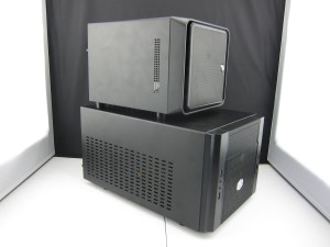
The parts arrived in short order, but once I saw the size of the case, I realized I was going to need to rethink things. The Cooler Master Elite 130 is well made and quite compact for a case that can take a full-sized video card, optical drive, ATX PSU and a CPU with a big heatsink/fan combination on top. Its pretty huge though for a machine with an external power brick and two hard drives. I started looking for other options and wasn’t too happy with what I found.

As far as I can tell, cases with just enough room for an mini-ITX motherboard and two 3.5″ HDDs don’t really exist, or if they do, they are bigger than I’d like and cost more than I wanted to spend. I started to consider cases with room for more drives. Most of them were about as big as the Elite 130, which could hold 3 full sized drives along with some 2.5″ drives, but it was still bigger than I wanted.

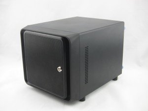
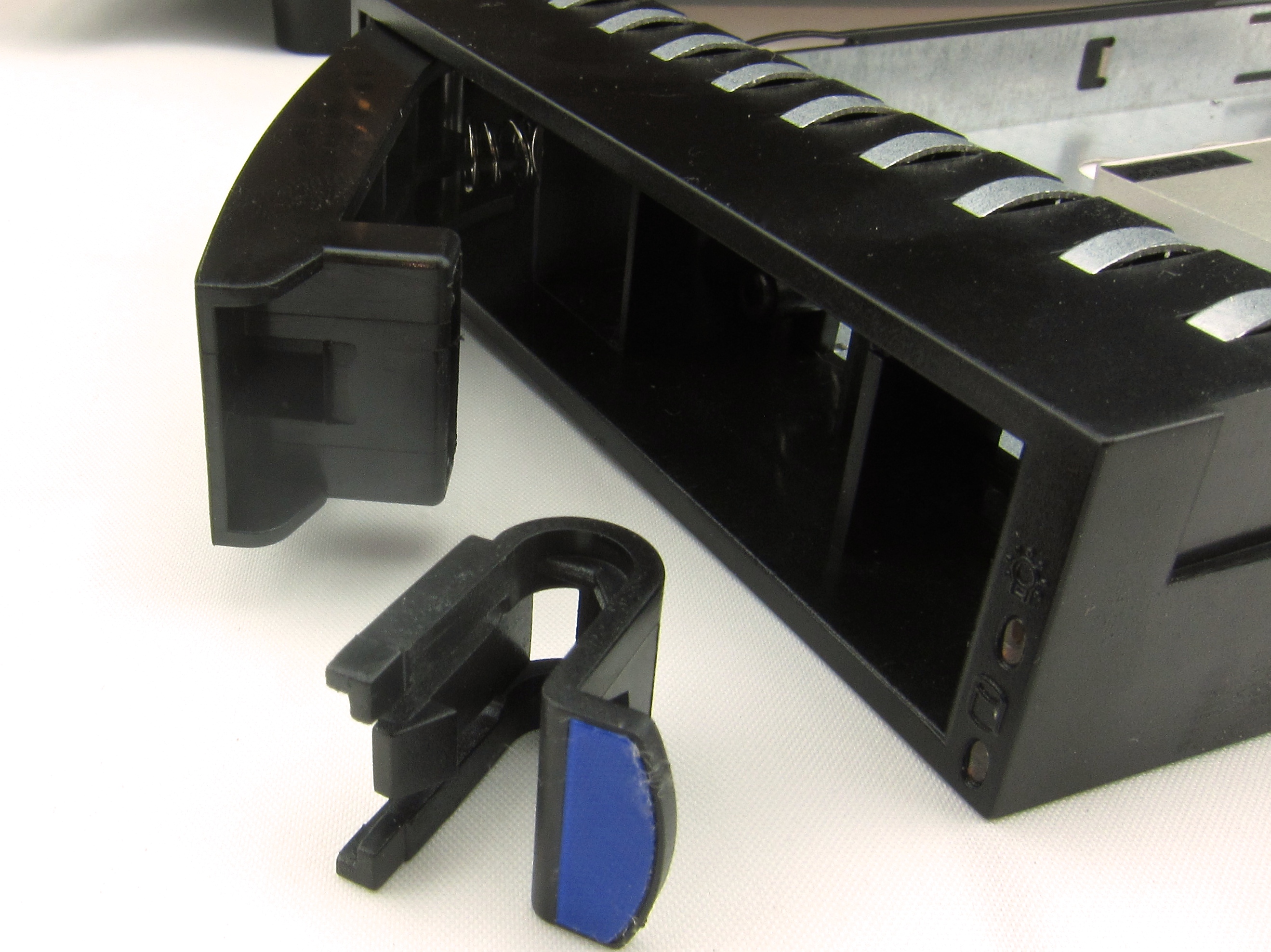
I also considered building my own case, and quickly rejected the idea, but kept returning to it over and over. Again, I decided to loosen the purse-strings to save time and energy, but there just weren’t many choices. I didn’t need hot-swap drive bays, but most of the small cases came with them. I finally settled on the Norco ITX-S4 case for $100.

At about this time I got a notification about a special price on the HP Microservers. The cost was ~$270. For that price, I got the whole machine, including 2GB of ECC protected RAM, ready for my hard drives. It was too late though, I was already in for $200. I bit the bullet and ordered the Norco case. Since I had the room for it in the case, I decided to move up my plan to use an SSD as a cache drive to speed up performance, and bought a a 256GB Crucial MX100 for $110.

Soon thereafter, the Microserver went on special at least two more times, but now I was in for $300 (not including the SSD). The ECC memory would have been nice though, and I seriously considered setting aside the  CPU, motherboard and RAM I already had and buying something that supported ECC. After spending, again, much too much time determining my options, I decided against it, because it would have cost another $300 or so, and my limit was $200.

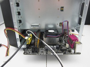
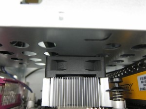
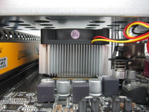
I wasn’t done yet though. Once I assembled the system in the new Norco case, I realized that I had another problem. The heatsink/fan combination that came with my CPU was too tall, and the space for it was too short — the top of the fan was pretty much flush with the bottom of the hard disk cage. Only now, as I’m writing this, do I realize that it would probably have been perfectly acceptable to Dremel cut a hole for the fan in the bottom of the HDD cage. Instead, I went looking for alternative CPU coolers that would fit better. There weren’t any, at least not any made for the AM1 platform. I took measurements and went looking for options that might fit, or that I could easily modify. I didn’t find much. I considered grinding down the top of the heat sink and reducing its height and cooling area by 10-20%, since it is a low-power CPU in a low-power application.

I was leaning towards ordering a generic heat-sink that would work with minimal modification when I realized a better solution. The stock fan was 15mm-thick. A 10mm-thick fan would open enough of a gap and solve my problem for less than $10 and 10 minutes work. Somehow though, the first fan I managed to order was also 15mm-thick…

The case had another problem too, the 80mm exhaust fan it shipped with was LOUD at full speed, and it ran at full speed ALL THE DAMN TIME because it only had 3 pins, and my motherboard required a 4-pin chassis fan for speed control (it does speed control on a 3 pin CPU fan though). This time though, I ordered the right thing, first time.

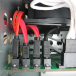
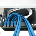
I did make another mistake though, I didn’t like my jumble of SATA cables and found them hard to route, so I decided to order some nice blue ones with round cables. Unfortunately, I missed the fact that they had 90° connectors on one end, which wouldn’t work with the positioning of the sockets on either the SATA backplane, or the motherboard. What’s more, the plastic molded on the ends of the cables was too thick, so 180° connectors wouldn’t have worked either. I ended up ordering more SATA cables!

Ah, but thats not the end of it. I decided to order a PCIe SATA card so I could mount the SATA drive on an internal bracket and save all the hot-swap bays for 3.5″ drives. I was happy to find an inexpensive card that used the same chip as the motherboard. Unfortunately, if I hook any devices up to it, Linux crashes on boot, shortly after detecting the device on the external card.

This post is long enough. I’ll document the actual build in a separate post after I have dinner.