CN3791 MPPT Solar Li-Ion Charger Module Hinky Circuit.

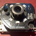
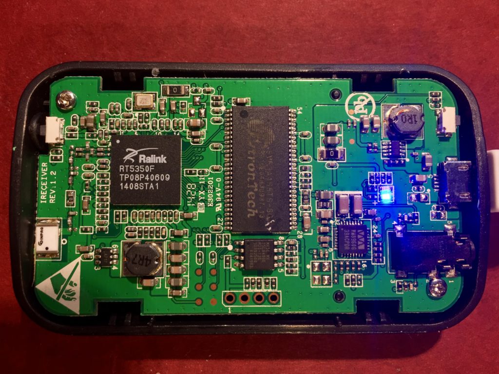
Last year, I paid about $3.66, with shipping, for this solar-powered MPPT lithium ion battery charging module on eBay to use with my small solar panels and scavenged 18650 batteries. It has some issues.

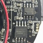
First off, the version I purchased/received is intended for 9v solar panels and I wanted to use it with a ~6v panel. This is set with a resistor divider. Careful study of photos from product listings showed that the divider was implemented using the same resistor value for the high segment of the divider, changing only the value of the lower segment’s resistor to change the setpoint.

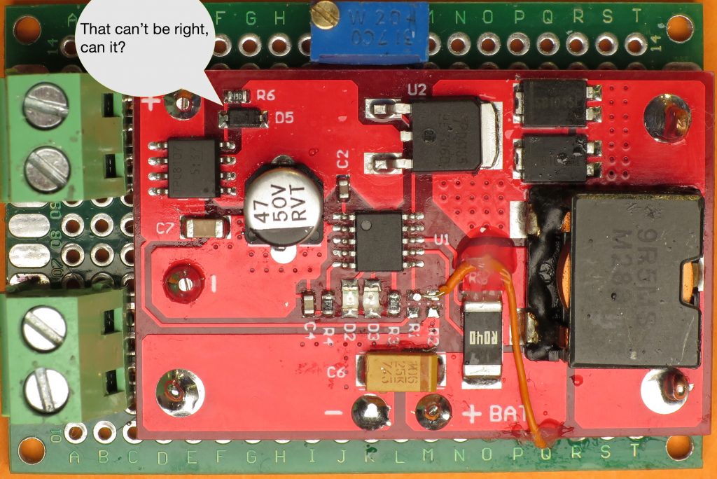
The high segment had a value of 178KOhm and the low ranged from ~42KOhm for a 6v panel down to 12.6KOhm for an 18V panel. I didn’t have any SMD resistors of suitable value in my supplies, and I couldn’t find any I could scavenge on any surplus PCBs. I decided to use a trimpot instead. I had a variety on hand, and it would allow me to experiment on the optimal clamping voltage for the panel I had on hand, and an 18V panel I’d ordered. I chose a 200KOhm trim pot with the idea that approximating the total resistance of the existing divider would help preserve the stability of the control loop. If I were going to do it again, I’d probably choose a different configuration to minimize the impact of the pot’s temperature sensitivity. A simple choice would be ~20KOhm trimpot, configured as a variable resistor (short the wiper to one terminal) used it to replace the low segment, leaving the 178KOhm resistor in place.

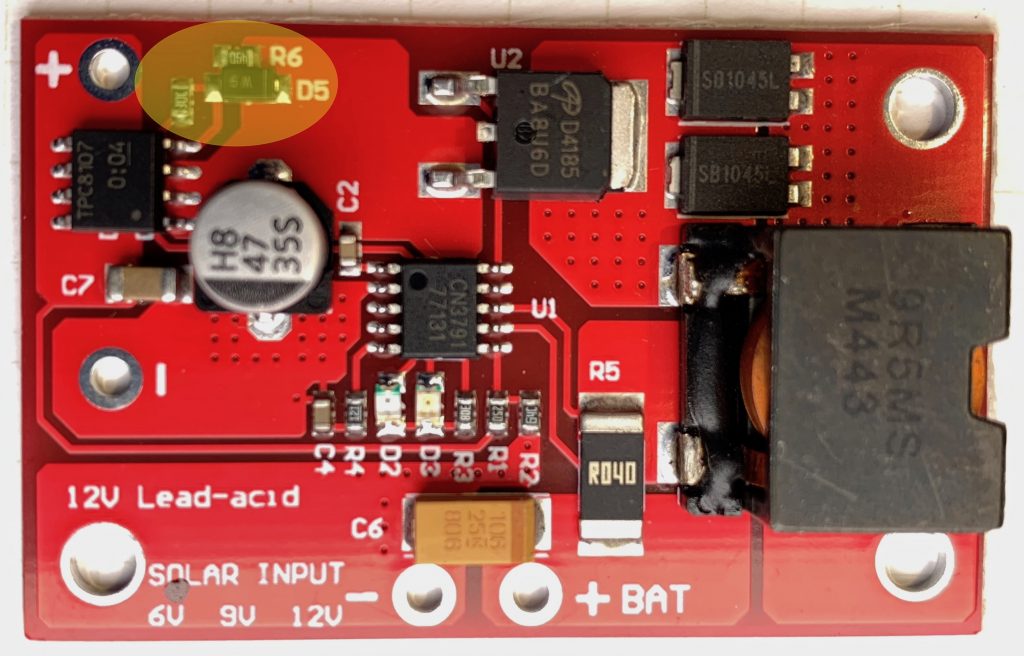
After adding the potentiometer, I connected the battery and panel and adjusted the potentiometer until I maximized the charging current. I was a little surprised by how low the panel voltage was, and so I started poking around. The first thing I checked was the voltage drop across a P-Channel MOSFET on the panel input. I was surprised to find that it was 500mV, though knowing that, I wasn’t surprised the IC was noticeably warm. The panel was dissipating 1/10th of the panel voltage over the MOSFET!

Some of the photos on some of the product listings showed a simpler circuit, without anything in the panel input current path. My guess is that the MOSFET and accompanying resistor and diode were added in a revision in order to protect the circuit in case the panel polarity was accidentally reversed, and/or to block leakage of charge from battery through panel at night. A schottky diode would accomplish the same thing more simply, but with a voltage drop of ~300mV. Properly implemented, a MOSFET based “ideal diode” would have an effective resistance of ≥ 50mOhm, and a voltage drop of ≥ 50mV at the ~1A max current my panel could deliver.

I’m not completely sure how the circuit was intended to work, but clearly, it wasn’t doing the job. I wondered if it would work properly if I was using the module with a 9V manual, as intended, but that didn’t seem possible, either. The panel + was connected to the MOSFET’s source, the rest of the circuit to the drain, and the gate was connected to the drain via a resistor and diode. By my reasoning:

  • that the gate would ≅the potential of the drain
  • the voltage drop from source to drain should be as close to 0V as possible in order to maintain the efficiency of the curcuit
  • therefore, Vgs would/should approximate 0V
  • but it won’t because the Vgs threshold for the MOSFET was ~2V!

I wasn’t sure how to fix the circuit, but I was sure that the gate needed to be pulled down to a lower voltage, so I cut the trace connecting the resistor the drain and connected it to ground instead. It worked well enough that the voltage drop over the input MOSFET went from 0.5V to a trivial number. I’m pretty sure though that I didn’t fix the protection function.

I’ve since received another version of the module which has revised the input circuit. The diode and parallel resistor connecting the gate and drain are still used, but there as another resistor which connects to the charging indication pin on the CN3791, and in so doing. This pin is open drain. When the battery is charging, it is pulled low, lighting the charge indicator LED AND pulling the input MOSFET gate low. Vgs ≅ -Vpanel ≅ Vs ≅-6V, turning the MOSFET fully on.

Thinking through this further… if the battery is charged and the panel is illuminated the gate will approximate the potential of the input MOSFET drain and, since the only load on the panel is the quiescent current of the module, then Vsd ≅ 0V ≅ Vgs and so the MOSFET will be off, save any current through the body diode.

If the panel is dark and the battery is charged then Vd of the input MOSFET will, at most, be at battery voltage (Vbatt), Vs will be ~0v, Vg will ≅ Vd, Vgs ≅ Vd and the input MOSFET will be off.

If the panel is reversed Vs will be below GND and well below Vg ≅ Vd ≅ Vbatt so Vgs will be Vbatt + Vpanel, and the MOSFET will be off. Note: This means that reverse polarity with an ~18V nominal panel would exceed the Vgs maximum of 20V for the TPC8107 MOSFET used at the input.

If I get around to it I’ll draw a schematic and add it to this post.

Digoo IP Camera Teardown and Links

I was just looking at unfinished posts and noticed that I’d taken, but not published, a bunch of notes I’d made earlier this year in hopes of hacking better firmware onto the Digoo BB-M2 WiFi PTZ Security Camera.I gave up on the quest, but here are my notes, with minimal editing.

Someone mentioned that the Chinese language page for Netcam360 has a link to the IPC-SDK. When I downloaded it and looked inside, I saw client-side code, but there was also a self-extracting archive called “HSmartLink Win32 SDK” and I remembered the PCB marking started with “HSL.” Searching for HSmartLink brings up hsmartlink.com, which, among other things, has IP webcams! The i9812 looks like a good match for my camera!

Unfortunately, no sign of any firmware updates. I checked the .cn version of the site too. It doesn’t seem as up to date on products (i9812 isn’t listed), and while there is more info in support section, it is still quite sparse. Page that looks like it is intended to link to downloads hasn’t been updated since 2015

Company is “Shenzhen Hsmartlink Technology Co. Ltd”

FCC Database listing for company

So what is the relationship to NetCam360 (check whois & IP ) and they mysterious APKLink?

Nmap Pobe

Starting Nmap 7.40 ( https://nmap.org ) at 2017-02-06 18:38 PST
Nmap scan report for 10.31.1.124
Host is up (0.0043s latency).
Not shown: 998 closed ports
PORT STATE SERVICE
23/tcp open telnet
81/tcp open hosts2-ns
MAC Address: E0:B9:4D:8F:61:6C (Shenzhen Bilian Electronicltd)

Nmap done: 1 IP address (1 host up) scanned in 0.49 seconds

Teardown Inventory

Photos

Ingenic

Module with Mediatek MT7601UN

Unknown

  • 15UDN8WY, ULN2803AG 18Pin in 2-row SMD
  • Darlington Transistor Array: http://www.ti.com/lit/ds/symlink/uln2803a.pdf
  • Probably used for driving PT motors

Atmel 542

  • 24C02N, SU27D
  • AT24C02
  • Two-wire serial EEPROM (2K)

Vertical PCB

  • SF1810-002, www.sufeitech.com. PCB antenna?

oosilicon or dosilicon?

Other

AirMobi iReceiver Preliminary Software Hacking

I recently discovered and purchased an inexpensive, unofficial WiFi-enabled AirPlay and DNLA audio receiver called the AirMobi iReceiver. I couldn’t find much information on the device, but for $12, I thought it was worth buying and trying.

It works reasonably well, but that’s not really why I bought it. I bought it with the intention of taking it apart and seeing what makes it tick. And now, having done that, I plan to hack it to run OpenWRT so I can secure it, customize it, and update the software.

IMG_9667

It is based on a Ralink RT5305T WiFi SoC which suggests to me that it is running linux, and probably has a serial console exposed via some test points on the mother board. I only found handful of candidates during my teardown. My guess was that the Tx and Rx lines were available on the unpopulated 4-pin header at the edge of the circuit board. From visual inspection I could tell that the second pin from the left was a ground pin. A little continuity probing with a multimeter suggested the first pin provided power, a fact confirmed when I check its voltage when I powered up the device.

I hooked a logic analyzer up to the other two pins to see which one toggled on and off at boot, but that was really overkill. I could have done just as well figuring out which one was pulled high when I powered up the device.

Once I had the pins worked out, I hooked up a TTL level USB/serial converter to my laptop, connected the ground pins and cross connected the Tx and Rx pins between the adapter and the board. Once I powered everything up, my screen started to fill with garbage. I guessed that 115.2Kbps was too fast, and tried 57.6Kbps instead. Bingo!

After booting up, I hit return and was presented with a login prompt. I tried the password for the webui and was pleased to find that it worked. I poked around the filesystem, looking at various config files, the various files for the web UI, and checking what binaries were installed on the system.

One of them is a telnet daemon (implemented as part of busybox). So, I started it, connected to the WiFi, and was able to log in over the network.

From there, I gathered more information. I was dissapointed that there wasn’t really anything like zip, or tar, or an ftp or ssh server that would make it easy to pull a bunch of files off at once, so I dumped the web UI files to the terminal one at a time and then saved them for further inspection.

Hidden ate_test.asp page

Hidden test_ate.asp page

Once I did, I found hidden functions in the firmware update page for uploading the bootloader over the webui. Exposing it required tweaking the page using web developer tools, which is kind of tedious. Then I hit the jackpot, I found an unlinked file called test_ate.asp. When loaded, it has a button to fire up the telnet daemon, making a command line available with just a WiFI connection, no serial console necessary. It also has an option to update the boot loader and a mysterious ATE function. This discovery made it easier to return and poke at the device at my leisure.

From what I learned in my poking and prodding, it appears to be based on the Ralink provided SDK with some modifications. With any luck, the modifications will be minor, and it will be easy to load an OpenWRT firmware over the webUI.

Before I do that though, I’ll need to take special care since this device doesn’t have an ethernet port, and so recovering from non-working firmware will be more difficult.

A lot of details follow…

Continue reading

AirMobi iReceiver Teardown

I’ve ended up with five small, inexpensive ($7-15 each) routers, running OpenWrt and only really need two of them, so I’ve been thinking of ways to use the others. One of my ideas was to get an external USB DAC, install Shairport-Sync, and use it as an AirPlay receiver for my car stereo, eliminating the need to connect an audio cable to my phone, and avoiding the mediocre sound quality of Bluetooth audio. It hasn’t quite worked out that way though…

While looking for an inexpensive (>$20), compact USB DAC with reasonable quality, I discovered there were integrated commercial products that already do what I planned to do. I already knew there were Apple-approved MFi-certified devices, but they tended to be expensive. I discovered there were cheaper devices using Shairport, but they tended to start at $30+.

Damaged while trying to open the case.

Damaged while trying to open the case.

With a little more digging though, I found a device called the iReceiver, from AirMobi that sells for as little as $12!!!. According to the scant marketing materials, it has a 24-bit Wolfson DAC. I was surprised I couldn’t find anyone who’d opened one up to see what was inside. I did find an Amazon review from someone complaining that the usb power connector had broken off on theirs, and the included photo showed it had a Ralink RT5350F WiFi SoC, which gave me hope that it would be hackable. So, I bought one.

Before opening it up, I tried it out. It works as promised. It defaults to broadcasting an unsecured WiFi network. Once connected, it shows up as an AirPlay receiver in iTunes, etc. From there, you can connect it to some powered speakers, select it and start playing music. The audio quality doesn’t suck (no obvious noise, clipping, or distortion), and in my limited use, there were fewer dropouts that I’m used to with Bluetooth.

Beyond that, there are various configuration options available through a browser based interface. There are no audio-related settings at all. Most of the settings are networking related. You can rename and secure the WiFi network with a password (good), WPS (bad) and by limited connections to specific devices by MAC address (meh). You can also connect to an existing network (good), and, optionally, extend it (meh). This seems like a good point to mention that it also works as a DNLA “renderer” (DNLA is a more open standard than AirPlay, making this useful to Windows and Linux devices, and Android phones with an appropriate app)

Of course, I didn’t buy it to use it with the stock firmware, so after trying it out, I opened it up to take a look inside. In the process, I managed to tear the translucent plastic that was affixed to the top of the case with adhesive. With the trim removed, it was easy to pry off the top, revealing the single PCB inside.

Version 2

As I expected, it is based on the obsolete but inexpensive and popular Ralink RT5350F WiFi SoC which includes a CPU and 802.11n WiFi.

  • Marked “RT5350F, TP08P40609, 1408STA”
  • 360MHz MIPS 24KEc CPU
  • 802.11n 1T/1R (1×1:1) 2.4 GHz 150Mbps MAC/BB/PA/RF
  • 5-port 10/100 Mbps Ethernet switch w/ 5 10/100 PHYs (unused)
  • USB 2.0 host/client (unused)

This is complimented by a modest, but sufficient 32MB of RAM and 8MB of flash memory to hold the firmware.

  • RAM
    • Marked: “EtronTech EM63A165TS-6G”
    • 255Mbit 16Mx16 5, 6, 7ns 166MHz SDRAM
  • Flash
    • Marked: “MXIC MX, 25L6406E, M2I-12G, 30392500, K141983”
    • Macronix MX25L6406E
    • 64Mbit NOR Flash
    • 4KB sector, 64KB block, 2.7-3.6v, H/W Hold
    • 1 or 2 bit bus, 86MHz x1 bus, 80MHz x2

The other major component is a Wolfson WM8960 CODEC to provide the audio output. This chip debuted in 2006, and includes 24-bit stereo DAC and ADC converters supporting sample rates up to 48Khz, a 40mW headphone driver, and a 1W Class D speaker driver.

Despite being a 24-bit DAC, the specified SnR of 98dBS matches that of the 16-bit TI/Burr Brown PCM2705 DAC used in the original AirportExpress, rather than of a modern, premium 24-bit DAC used in more recent AirportExpress’s. Oh well. Good enough for my purposes. Most of what I’m playing is compressed AAC files derived from 16-bit sources, and, AirPlay only passes 16-bit anyway. Beyond that, the design of the rest of the circuitry matters, and I’m not qualified to analyze it, nor am I equipped or inclined to try and measure it.

Beyond that, I see two inductors on the board (one of which is cracked). My guess is that these are part of some small switch mode power supplies, perhaps one for the digital section, and the other for the analog. There are two small LEDs to indicate device status and two momentary switches, one to reset the device, and the other to trigger WPS. It looks like it uses a single ceramic chip antenna for the WiFi.

There are a few unused pads for components, eight test points (half seemingly to do with power) and four unused holes for pin headers that I suspect provide a serial console.

That’s really it for the hardware. I’ve already started poking more deeply into the software and investigating the suspected serial console, and I hope to have another post soon documenting what I found.

IMG_9679

iReceiver Elsewhere