Solar Panel Notes

I’ve been tinkering with a small, semi-potable solar setup and have an eye to upgrading it. These are my notes. My facts my be incorrect, they are certainly incomplete.

My system is currently configured as:

  • 18W, 18v flexible Sunpower panel.
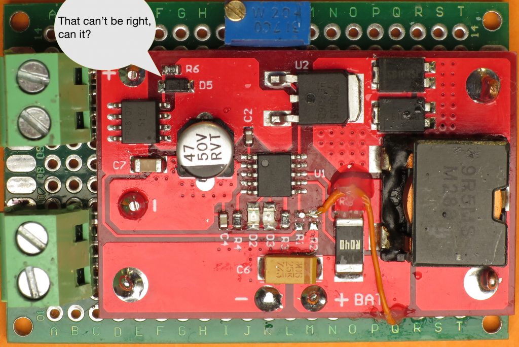
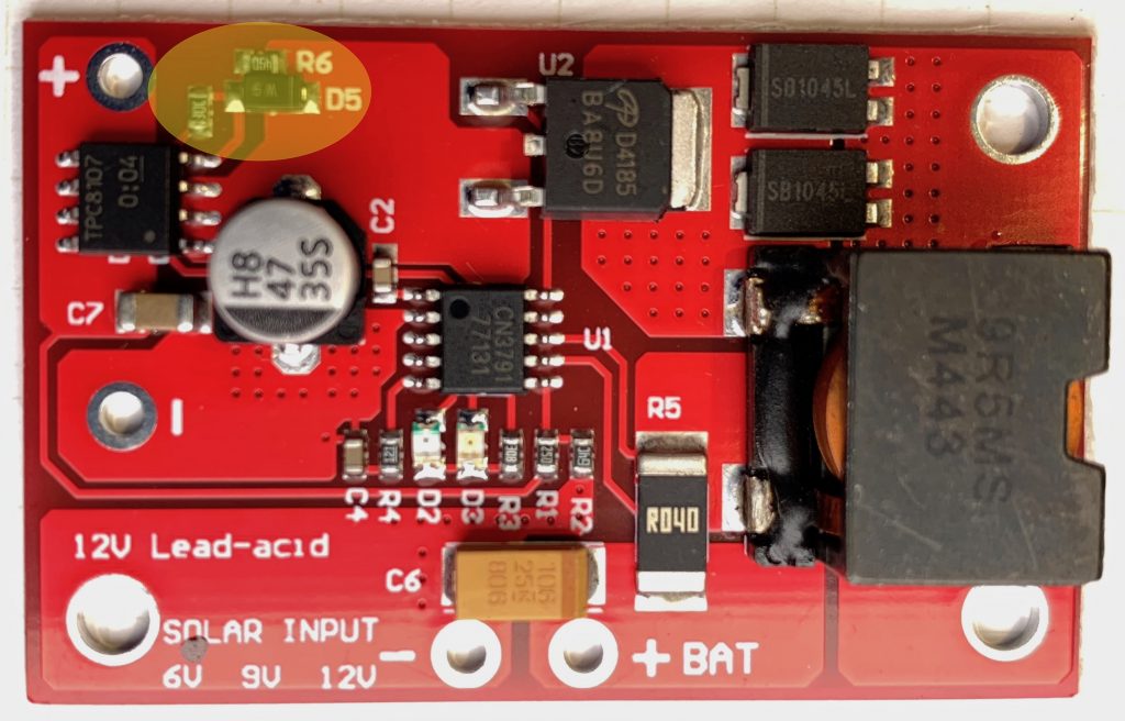
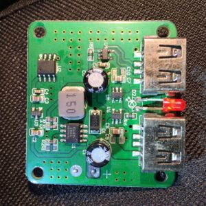
  • CN3791 MPPT charge controller
  • LiIon battery pack(s) made from 1S20P Samsung 28A 18650 cells. Configured as two packs of 1S6P and one pack of 1S8P, each with a cheap protection board. Estimated capacity is ~150Wh
  • ~15W 6v folding, portable panel, made from Sunpower cells. I’ve added a bypass for the buck converter that supplies regulated 5V USB so I can use it with MPPT controllers.
  • 21W 6V folding, portable panel, made from Sunpower cells. I’ve added a XT30 connection so I can swap in different loads, including the original 5v USB buck regulator, a different buck regulator, or an MPPT controller.
  • These folding panels are hooked up parallel, they are connected to another CN3791 MPPT charger.
  • Both chargers are connected in parallel to the battery bank. This could have some weird effects, particularly as the pack reaches 4.2v and goes into constant voltage mode.

The panels are not optimally deployed. They are lying flat, and due to trees, etc, only get unobstructed sun for ~4-6 hours a day. In this arrangement, peak power for the 18W panel has been about 10-12W.

The 6v panels are even more suboptimally deployed due to sitting on the floor of a window platform for cats, which means they are obscured at times by the frame and even the 18W panel which rests above them.

I also have a laminated ~6W 5V Sunpower panel that is currently unused. It originally had a buck regulator to power USB devices, but I removed it and replaced it with a quick release terminal so I can use it directly with a battery charger.

I’d like to move up to 100-200W of panel capacity before a new wave of Trump’s dumbass tarifs hit. Options in consideration:

  • Rigid mono or polycrystalline panels.
    • Polycrystalline is currently slightly cheaper per nameplate wattage, but maybe not enough to be compelling. Currently <$1/W.
    • Pro: Cheapest option. Con: Since I’m not making a permanent installation, the fact their weight and fragility of the glass is a concern.
  • Flexible panels. Lots of options, most of them dubious.
    • The cheapest flexible panels are available at a ~20-50% premium over rigid panels.
      • Use PET encapsulation on the sun-facing side, which isn’t suitable for constant environmental exposure.
      • Use cell constructions that don’t hold up to flexing and don’t deal well with microcracks that develop in the silicon wafer due to flexing.
      • Use panel interconnects that won’t hold up to flexing.
    • Quality flexible panels are 2-3x as expensive as cheap rigid panels.
      • Use EFTE top layer for long life and durability.
      • Use primarily Sunpower, but occasionally Day4 or Merlin cells which are well suited for the challenges of flexible substrates.
      • Use rugged, flexible interconnects.
    • Folding flexible panels.
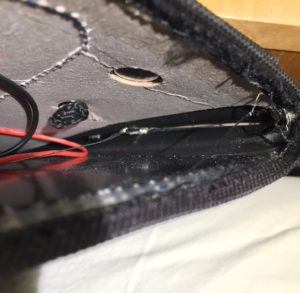
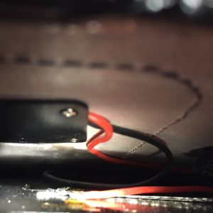
      • One, common variety uses ~6v, 7W subpanels connected in parallel to power a 5V USB buck regulator. The subpanels are made from twelve Sunpower offcuts in series. These are typically encapsulated in PET and sewn into ballistic nylon covers with cardboard for added stiffness. Newer designs use EFTE and may forgo the fabric construction a fully laminated construction and a panel thickness of 2-3 millimeters..
      • $1W at the low end, >$2W for branded products like Anker or RavPower.

Background Information

  • Panel Basics
    • Solar panels are constructed from multiple photovoltaic (PV) solar cells in series.
    • A typical PV solar cell has an optimal voltage of about 0.5-0.6v, which is determined by the bandgap of the doped silicon junction.
    • The number of cells assembled in series determines the panel voltage.
    • Panel voltages are generally matched to their intended application.
      • Six cells in series (6S) are well suited for 3V electronics of the sort powered by two Alkaline cells in series or a single lithium metal cell (like the ubiquitous CR2032 button cell.
      • Ten (5V) to twelve (6V) PV solar cells in series are typically used to charge/power 5V USB devices by way of a buck-converter voltage regulator. These configurations are also well suited to charging Lithium Ion batteries, which are used in smartphones and most other battery-powered devices that can be charged from USB.
      • Panels made from 32-36 cells in series are common. They have an optimal voltage of 18V, but are often labeled as 12v because they are used to charge 12v lead acid batteries without a regulated charging circuit. The are also used with LiIon batteries in conjunction with a suitable charging controller. ~100W, 18V panels are often connected in series for higher-voltage and higher powered systems, including AC systems
      • 150-300W panels with 50-72 PV cells in series are also used in larger installations.
    • Panel Construction
      • Panels are assemblies of multiple, electrically interconnected, solar cells. They protect the component PV cells from the elements, and provide support when deploying and mounting the cells
      • Rigid
        • Framed Laminate panels sandwich the cells and their interconnects between glass and a sturdy backing material. The laminated panel is then held in an aluminum frame to enhance rigidity, provide protection, support and points of attachment for mounting the panel.
        • Cast panels are typically under a few watts of power. They seal the cell in protective epoxy or another cast resin.
      • Flexible
      • Laminated

GL-Inet GL-MT-300Nv2 Power Consumption

Today I updated the firmware on my GL-Inet MT-300N v2 “Mango” travel router, and while I had it out I decided to measure its power consumption.

For those who don’t know, a travel router makes it easier to securely use a temporary internet connection, like that provided by a hotel, and share it among multiple devices. The hardware specs on the GL-MT-300Nv2 are modest, but sufficient, it is compact (about the volume of a deck of playing cards), and inexpensive ($20.49 on Amazon). The firmware is based on a recent release of OpenWRT with a UI optimized for use as a travel router. For those who want it, the standard OpenWRT Luci interface is available.

I decided to test the power consumption because my tiny solar power station (~18W panel, 120Wh LiIon battery), was generating more power than it could store and I’d already finished charging my phone for the day. As I unplugged my phone’s charging cable, I noticed that the USB-powered router was right there, so I plugged it in instead and reset my USB power meter.

Once the router started up and I connected my laptop to it over wifi, I noted the power consumption was about ~1.3-1.5W. I ran an Internet speed test from my laptop and the power consumption bumped up slightly. After an hour, the cumulative power consumption was ~1.4Wh. I connected the router to ethernet to see if that made an obvious difference in the power consumption; it didn’t.

Based on these crude measurements, I think it’s safe to say that the GL-Inet GL-MT-300Nv2 uses less than 2W on average. That means that, if necessary, it could run for >3h off a typical small USB power bank, and could probably run directly off a ~$15 6-7W solar panel with USB output through most of a summer day.

I didn’t check the power consumption while using the router as a VPN gateway, which is probably the most CPU intensive use of a travel router. The manufacturer’s specs for power input are 1A @ 5v, which works out to 5W, so thats the limit on peak power draw, and would only be reached during the peaks of VPN use. Peak VPN speeds are in-turn limited by the CPU’s performance, which limits peak VPN speed to ~10Mbps.

CN3791 MPPT Solar Li-Ion Charger Module Hinky Circuit.

Last year, I paid about $3.66, with shipping, for this solar-powered MPPT lithium ion battery charging module on eBay to use with my small solar panels and scavenged 18650 batteries. It has some issues.

First off, the version I purchased/received is intended for 9v solar panels and I wanted to use it with a ~6v panel. This is set with a resistor divider. Careful study of photos from product listings showed that the divider was implemented using the same resistor value for the high segment of the divider, changing only the value of the lower segment’s resistor to change the setpoint.

The high segment had a value of 178KOhm and the low ranged from ~42KOhm for a 6v panel down to 12.6KOhm for an 18V panel. I didn’t have any SMD resistors of suitable value in my supplies, and I couldn’t find any I could scavenge on any surplus PCBs. I decided to use a trimpot instead. I had a variety on hand, and it would allow me to experiment on the optimal clamping voltage for the panel I had on hand, and an 18V panel I’d ordered. I chose a 200KOhm trim pot with the idea that approximating the total resistance of the existing divider would help preserve the stability of the control loop. If I were going to do it again, I’d probably choose a different configuration to minimize the impact of the pot’s temperature sensitivity. A simple choice would be ~20KOhm trimpot, configured as a variable resistor (short the wiper to one terminal) used it to replace the low segment, leaving the 178KOhm resistor in place.

After adding the potentiometer, I connected the battery and panel and adjusted the potentiometer until I maximized the charging current. I was a little surprised by how low the panel voltage was, and so I started poking around. The first thing I checked was the voltage drop across a P-Channel MOSFET on the panel input. I was surprised to find that it was 500mV, though knowing that, I wasn’t surprised the IC was noticeably warm. The panel was dissipating 1/10th of the panel voltage over the MOSFET!

Some of the photos on some of the product listings showed a simpler circuit, without anything in the panel input current path. My guess is that the MOSFET and accompanying resistor and diode were added in a revision in order to protect the circuit in case the panel polarity was accidentally reversed, and/or to block leakage of charge from battery through panel at night. A schottky diode would accomplish the same thing more simply, but with a voltage drop of ~300mV. Properly implemented, a MOSFET based “ideal diode” would have an effective resistance of ≥ 50mOhm, and a voltage drop of ≥ 50mV at the ~1A max current my panel could deliver.

I’m not completely sure how the circuit was intended to work, but clearly, it wasn’t doing the job. I wondered if it would work properly if I was using the module with a 9V manual, as intended, but that didn’t seem possible, either. The panel + was connected to the MOSFET’s source, the rest of the circuit to the drain, and the gate was connected to the drain via a resistor and diode. By my reasoning:

  • that the gate would ≅the potential of the drain
  • the voltage drop from source to drain should be as close to 0V as possible in order to maintain the efficiency of the curcuit
  • therefore, Vgs would/should approximate 0V
  • but it won’t because the Vgs threshold for the MOSFET was ~2V!

I wasn’t sure how to fix the circuit, but I was sure that the gate needed to be pulled down to a lower voltage, so I cut the trace connecting the resistor the drain and connected it to ground instead. It worked well enough that the voltage drop over the input MOSFET went from 0.5V to a trivial number. I’m pretty sure though that I didn’t fix the protection function.

I’ve since received another version of the module which has revised the input circuit. The diode and parallel resistor connecting the gate and drain are still used, but there as another resistor which connects to the charging indication pin on the CN3791, and in so doing. This pin is open drain. When the battery is charging, it is pulled low, lighting the charge indicator LED AND pulling the input MOSFET gate low. Vgs ≅ -Vpanel ≅ Vs ≅-6V, turning the MOSFET fully on.

Thinking through this further… if the battery is charged and the panel is illuminated the gate will approximate the potential of the input MOSFET drain and, since the only load on the panel is the quiescent current of the module, then Vsd ≅ 0V ≅ Vgs and so the MOSFET will be off, save any current through the body diode.

If the panel is dark and the battery is charged then Vd of the input MOSFET will, at most, be at battery voltage (Vbatt), Vs will be ~0v, Vg will ≅ Vd, Vgs ≅ Vd and the input MOSFET will be off.

If the panel is reversed Vs will be below GND and well below Vg ≅ Vd ≅ Vbatt so Vgs will be Vbatt + Vpanel, and the MOSFET will be off. Note: This means that reverse polarity with an ~18V nominal panel would exceed the Vgs maximum of 20V for the TPC8107 MOSFET used at the input.

If I get around to it I’ll draw a schematic and add it to this post.

Balight 21W Folding Solar Panel USB Charger Partial Teardown

I picked up a 21W, 3-panel Balight folding solar panel-based USB charger from Amazon for ~$36 a couple of weeks back. It uses high-efficiency SunPower Maxeon cells much like similar 20-21W panels from AukeyAnker and dozens of obscure brands. All of them have the same basic construction. They are all made from nylon ballistic cloth. Each fold has a panel made from two SunPower cells encapsulated in a flexible waterpoof sheet. The panels provide power via two 5v USB ports, which presumably have some sort of voltage regulator.

I wanted to know more about how the chargers worked. In particular, I wanted to know if they were wired in series, or parallel because I wondered if it was worth trying to tap into the raw output, before the USB regulator to reduce power conversion and resistive losses for some applications.

I thought I’d be able to get the information I needed by finding someone documenting a teardown of their own panel on YouTube or a blog post. Despite the dozens of variants from dozens of brands and a handful of manufactures though, I didn’t find what I was looking for.

So, I decided to dig up a seam ripper and open my panel far enough to get a look at the wiring, and tap in to it upstream of the voltage regulator.

The panels appear to be wired together with some sort of woven wire conductor. I had some hope that all the cells would be wired in series, to give a nominal panel voltage of 18v. Based on what I could see, and measuring the voltage before the regulator in full sun, it looks like each panel is wired in series, for 6v nominal voltage, and then the panels are wired together in parallel. I was disappointed at first, but this arrangement makes sense in upon further thought.

Using a 2s3p configuration means that the input voltage into the switching regulator should be pretty close to the 5v (actually, 5.2v with enough sun and a light enough load) output of the USB power regulator, which will typically have higher conversion efficiency than 12 or 18 volts. It also means that the manufacturers can stock one converter for everything from a 7W single-panel charger, up to a 28w 4 panel charger without the converter having to support a wide range of input voltages. Perhaps most importantly, it means that partial shading of one panel shouldn’t have a disproportionate impact on the power output of the entire array.

The only downside is that resistive losses in the cabling will be higher with lower voltage and higher current, but that the interconnects aren’t more than a foot or so, the resistive losses shouldn’t be too high.

As for the converter itself, I may look at it more closely and add some more details, but, a few initial observations:

  • The PCB design has extensive ground planes on top and bottom, tied together with vias.
  • Both outputs are served from a single buck-converter (step-down) power supply based on a Techcode TD1583, which is a 380 KHz fixed frequency monolithic step down switch mode regulator with a built in internal Power MOSFET.
  • It looks like only port 1, at the top right in my photo, has the data lines connected, which suggests that it is the only one with fast-charge coding.
  • IC U2 looks like it has its markings sanded off. I notice though that one of its pins is connected to the enable pin on the TD1583, leading me to think that it is responsible for cycling the output to make sure devices draw as much power as possible when the panel voltage rises again after clouds or an object reducing the light falling on the array pass. I don’t know if it is a MCU, some sort of timer, or comparator, or what, though.

There you go. I can’t be sure that other folding solar arrays like this one are wired in the same way, but if they only support a 5v output, I suspect they will be. I hope this proves useful to someone besides me.