I already have more working electronic lab equipment than I need, and more broken equipment than I can fix in the next month or so, but I still check eBay daily, and occasionally, I see a deal that is too good to pass up. This time, it was an Hewlett Packard 6114a power supply on sale for $75 + $19 shipping. The supply had been listed for $150, and I figured that if the seller was willing to cut the price in half, they might be willing to accept even less. I offered $55.
I’m really not sure what I was thinking. Part of me felt like getting the supply for $75 would be a great deal. Part of me thought that not getting it at all would be smart, since I didn’t need it, and had resolved not to take on other projects. Part of me wanted to see if I could get it for even less. In the end, it looks like the compromise I made was to try and serve all three, because I picked a price that was low enough that it might not be accepted, but high enough that I might end up with another piece of equipment. And so I did.
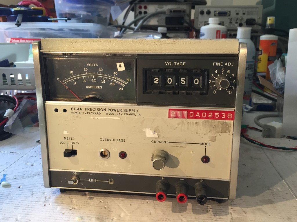
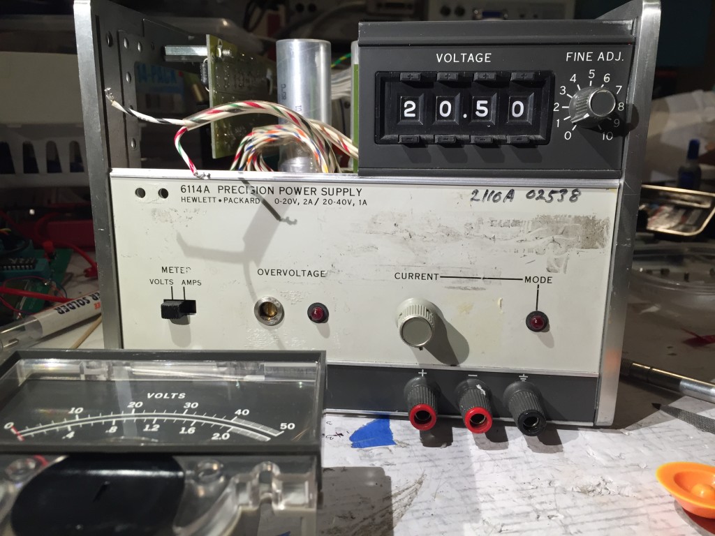
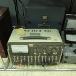
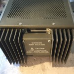
The HP 6114a was introduced in in the early 1970s and produced until at least the early 1990s. They typically go for something over $100 + shipping, so getting one for just under $75 would rate as a good but not great deal. From the photos in the listing, I thought I could make out enough of the serial number to tell that this example was made in 1981, a fact I confirmed once it arrived. It had the base single-turn potentiometer for the current control, rather than a 10-turn pot with a turn-counting dial, but I thought I could upgrade it myself for $10-20 in parts.
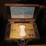
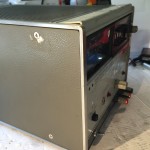
Physically it seemed in fair shape. There were some bent fins on the heatsink, and the front panel trim wasn’t seated properly, and might need to be bent back into shape. Most of the finish seemed to be in good shape. The condition of the front panel was harder to judge. It was hard to tell what was sticker residue and what was scratches in the finish.
The unit arrived from Nevada about three business days after I ordered it. It was packed in a stout cardboard box, and heavier than I expected. Inside I found it wrapped in a few sheets of thin foam, nestled in a reasonable amount of packing peanuts. I think there were enough peanuts to protect the instrument as shifted in the box transport, but I’m not 100% sure, because there was some damage to the front panel and its hard to tell if it was pre-existing, or it occurred during shifting.
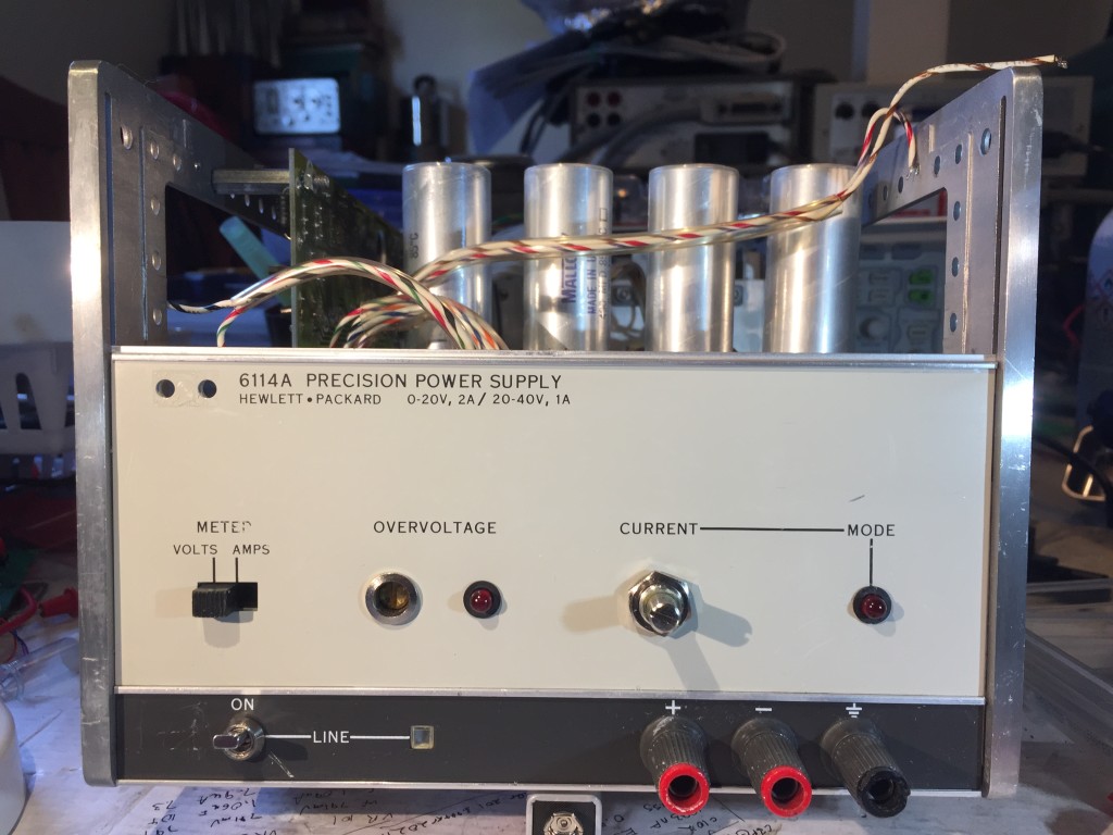
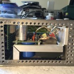
There weren’t any big surprises after I got it unwrapped. Next step was to start taking it apart so I could figure why the top trim on the front panel wasn’t seated properly, and what I could do about it.
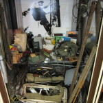
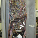
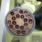
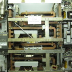
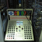
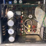
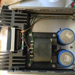
Along the way, I also performed an initial inspection of the electronics to look for damaged components, PCBs and interconnect wires.
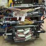
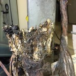
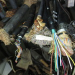
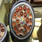
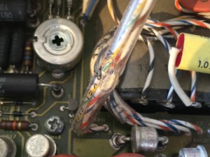
I quickly spotted some damage to some of the pvc tubing used for cable management (above left). It looked like it had been scorched by an errant soldering iron, suggesting a previous repair. It took my a while to figure out that the site of the repair was (probably) right there in front of me. That a big resistor (above right) is not like all the other big resistors. It’s epoxy packaged. The rest are ceramic.
My deeper inspection showed that displaced top trim wasn’t bent, as I feared. The aluminum extrusion was in good shape, other some chips and gouges in the finish, some of which had cut into the underlying aluminum. With the top trim removed, I could take a closer look at the other components of the front panel.
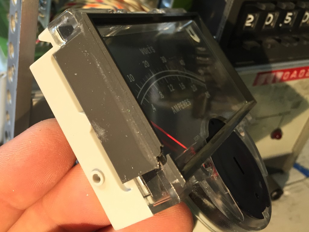
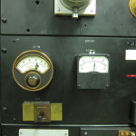
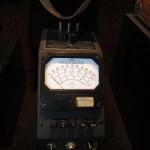
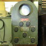
The meter was in pretty good shape, but its grey plastic bezel, which also served to help retain the clear plastic lens piece, was broken in the lower left hand corner. I removed the bezel and glued the crack with some superglue. Once it was dry, and sanded it down and polished it with some nail files/polishers I got surplus from my wife. The crack is still visible if you look closely due to glue filling in fit is repaired and the profile and finish of the plastic is pretty close to what it originally was.
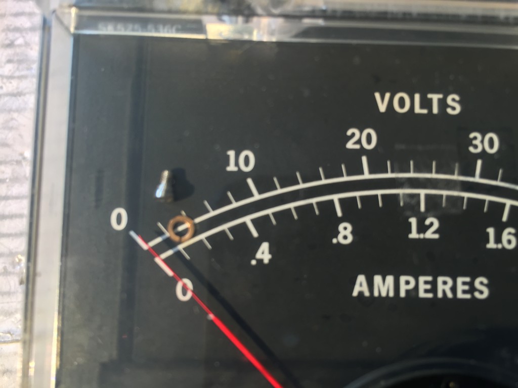
During initial inspection, I noticed a rattle as I turned the instrument over. As opened the chassis up, I was attentive to the source of the noise, but couldn’t pinpoint it. In the process of removing the meter bezel, I realized the loose part was in the meter. I desoldered the meter leads so I could inspect the meter more easily. As I did, the source of the rattle quickly revealed itself to be small screw and copper lock washer. Once I had the meter free of its leads, I removed a clear plastic clip holding the meter lens to the back of its housing and worked the lens loose. With it free, I could see the source of the loose parts, they were one of the pair fastening the printed meter dial to the frame of the brass meter mechanism. They’d somehow worked themselves loose.
The copper washer dropped out as soon as I opened the meter housing, but I lost track of the screw. It wasn’t on my workbench, and gentle tapping of the meter housing didn’t shake it loose. I went in search of a suitable tool for removing the recessed nuts at the back of the housing that hold the mechanism to the meter. The socket wrenches I had were too thick-walled, but a fine set of needle nose pliers ended up doing the job. I still couldn’t find the screw though. I pulled the internal leads free of the pins that passed through the housing so I could take a closer look. Perhaps the screw had found a spot inside the works of the mechanism? After 15-20 minutes, I concluded that it must have dropped out as I carried it in search of a wrench. After searching around on the floor around my chair for 10 minutes, I broadened my search area and almost immediately spotted it camouflaged in a dust bunny on the other side of the table, along the path I took to the basement to look for tools.
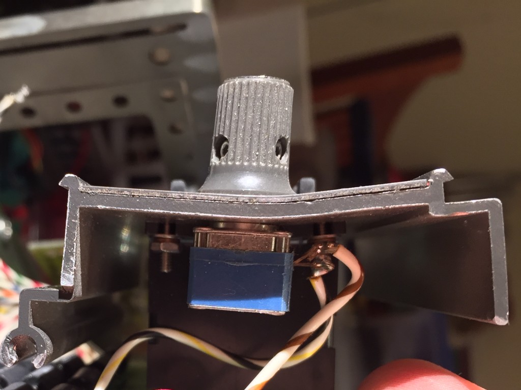
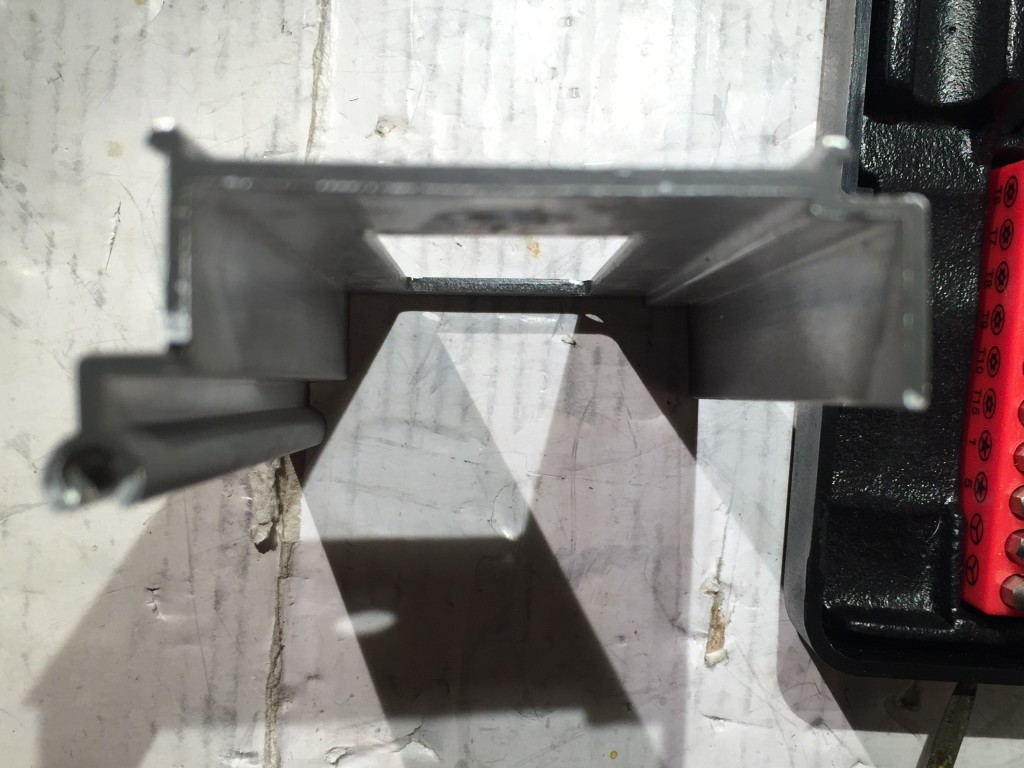
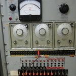
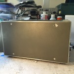
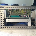
After reassembling the meter, I decided to remove the one screw holding the voltage control subpanel to the chassis and take a closer look at it. That doesn’t look right, does it? That bow isn’t lens distortion, that’s bent aluminum. I can’t tell from the photos in the listing if the damage was already done, or if it happened in transit. One way or another, it looks like the result of sliding or being pushed face-first against something.
In preparation for repair, I desoldered the two leads connecting the voltage control to the main PCB. One connected into a PCB on the sub assembly and was easy to remove. The other connected directly to a lead on the potentiometer shown in the photo. It was a bit fussy. The leads from the pot are basically ~22 gauge wire with a hairpin bend at the end. To get the wire free, I ended up removing most of the solder with some desoldering wick, and then alternated between teasing the hairpin open and working the wire free. All in all, it was fussier than I would have liked, and I ended up scorching some of the plastic potentiometer housing when I accidentally touched it wit the side of the soldering iron. In retrospect, i should have removed the knob and unscrewed the pot from the front panel before trying to desolder the lead.
With the assembly free, I removed the knob and retaining nut on the potentiometer, then I heated the aluminum carefully with a hair dryer so it was easier to pull the thinner front sheet with the labeling free of the the thicker extrusion so that I could get to the screws holding the decade switches.
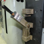
With the bent extrusion isolated, I used a hammer and a few hardwood blocks to carefully beat it back into some semblance of flat. I think I did a pretty good job.
I also spent some time cleaning the stickers and adhesive off the remainder of the front panel. I started by peeling off what I could, which revealed some writing with permanent marker. Isopropyl Alcohol on some cotton balls and a little elbow-grease took care of all the adhesive and faded the permanent marker.
I used an old “drafting” eraser to rub out the last remnants of the magic marker and a few persistent spots. I think its looking pretty good. There are a few tiny scrapes in the white panel, and a few more in the grey strip at the bottom that I think I’ll leave be. Some of the lettering on the white panel is a little worn. I might try touching that up.
The most glaring problem is the missing HP logo badge that is supposed to fit over those two holes in the upper left of the panel. Given the vintage of this supply, I think the original logo badge had charcoal and gray with a chrome border. Anyone happen to have any spares?
Next step, I think is to put it back together and check to see how it works.
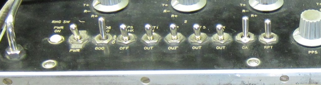
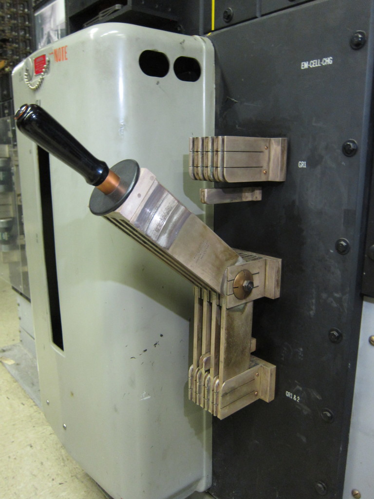
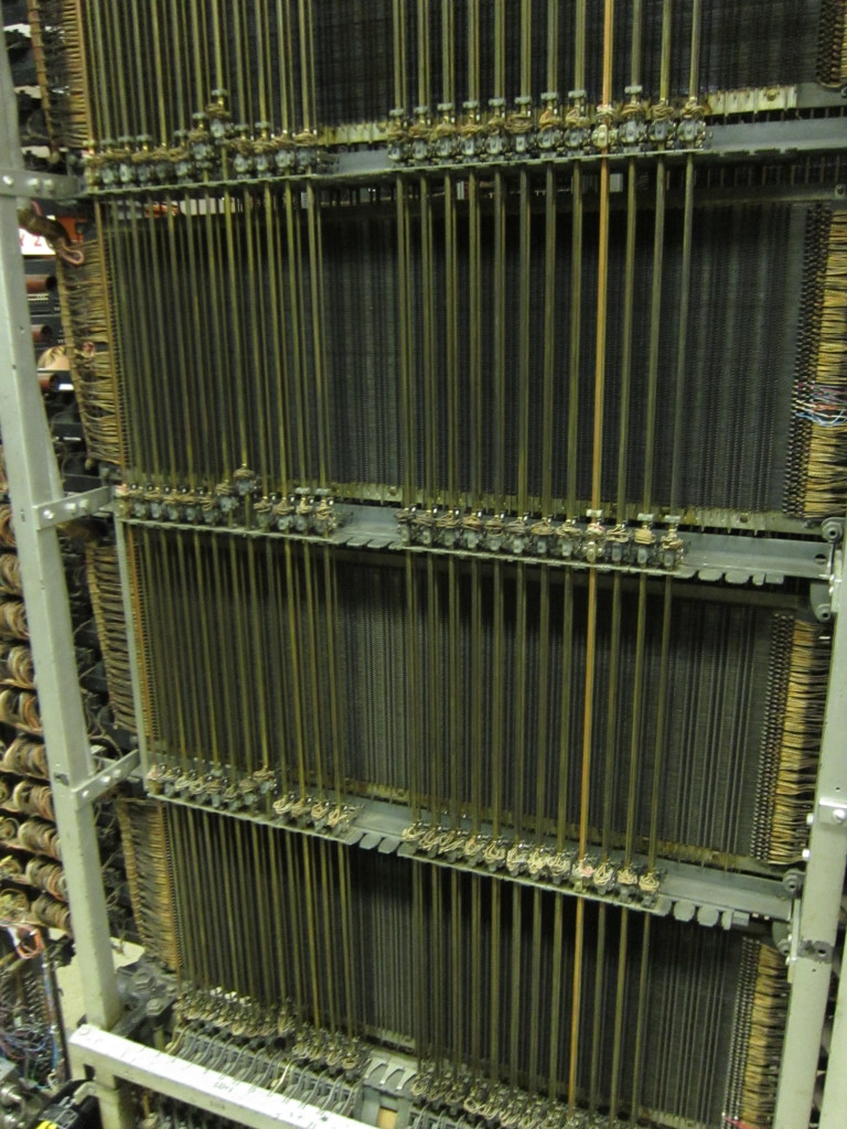
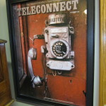
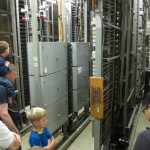
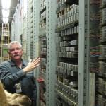
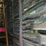
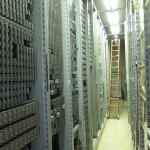
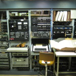
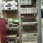
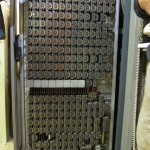
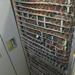
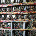
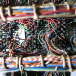
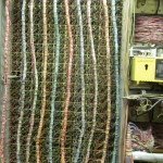
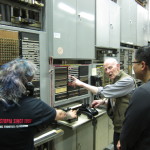
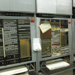
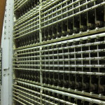
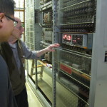
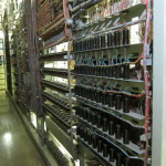
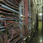
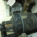
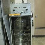
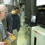
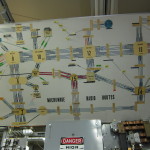
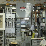
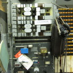
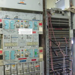
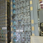
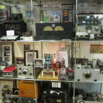
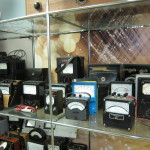
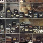
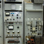
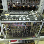
 It is part of a panel telephone switch, one of a number of operational telephone switches at The Herbert H Warrick Jr. Museum of Communications, a little known technological treasure trove in the Georgetown neighborhood of Seattle. The museum fills the top two floors of a Century Link central office building.

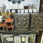
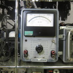
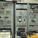
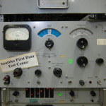
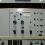

 The seller described the unit as used with responsive controls and indicators. When I received it, I could see that while in generally good physical shape the upper right portion of the front panel was more bent/buckled than I could make out in the eBay photos.
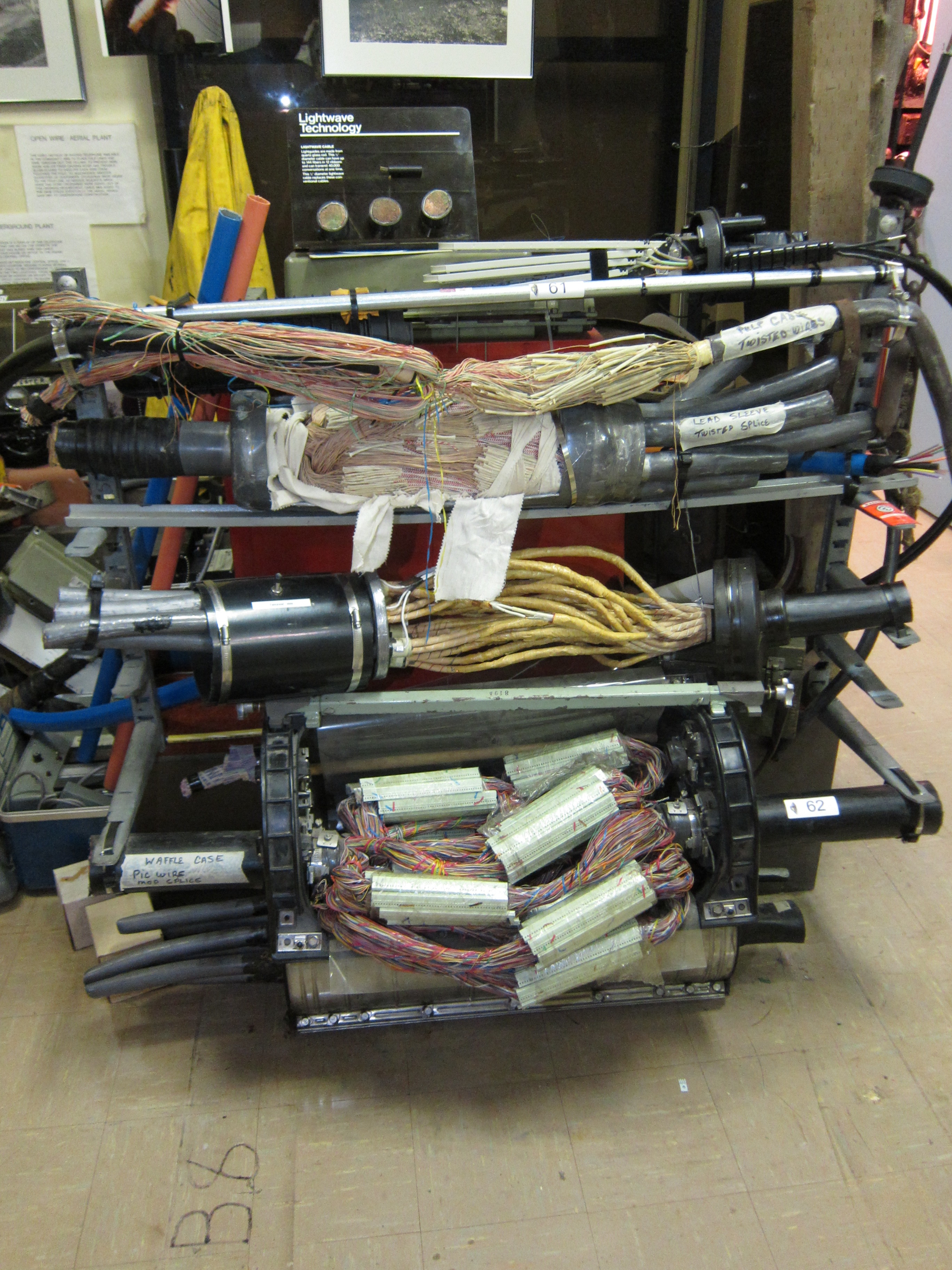