Update: I made a major revision to The Conduit Amp with some improvements and a bit better fit and finish.
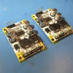
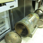
A few months ago I was at the hardware store looking for cheap enclosures for electronics projects. Some aluminum junction boxes for electrical conduit caught my eye, so I bought a couple. In parallel, I was interested in building a small, portable amp that could operate off 12v, which led me to buy some little, mono, TPA3110 modules for a few bucks each.
Surveying my box of parts a couple weeks ago, I noticed that the TPA3110 modules would fit nicely in the smaller of the two junction boxes I purchased, and I started tinkering with ways to assemble them into a finished product.
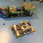
The first idea was to join the boards together with standoffs and slip them inside. I ordered some small terminal blocks for the electrical connections. When they came, though, and I tried assembling things as I planned, I realized I’d need to cut the standoffs down in order to fit a board to hold a potentiometer. I was feeling lazy, and didn’t want to deal with metal filings, so I looked for another way.
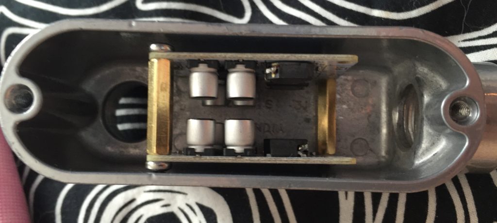
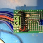
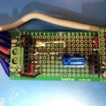
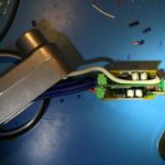
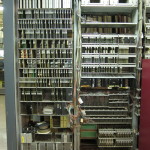
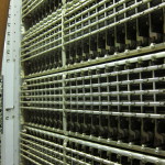
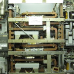
I decided to use pin-headers to mate the amp modules with small motherboard made from perfboard. For added mechanical strength, I cut the headers with more pins than needed, soldered the pin positions with through-holes on the amp board, and then glued the rest and trimmed them to the same length as the active pins.
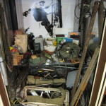
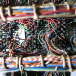
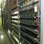
Routing the power input and speaker outputs was kind of a nightmare. Rather than trying to plan it all out, I ended up working a couple of connections at once, trying to leave room for the other connections. It took quite a while. I was concerned about some of the routing and figured I’d probably end up doing a second version, so I soldiered on soldering my prototype.
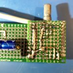
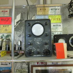
Once I was done, I used my multimeter to check to make sure that there weren’t any short circuits on the motherboard. Fortunately, everything checked out.
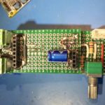
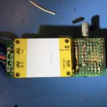
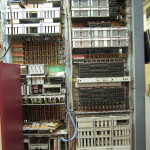
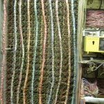
Next I had to finish up the input connections and passive volume control. Rather than routing the audio input on the protoboard, I decided to take advantage of the shielding on the input to help keep the signal clean while passing the high-current power and output connections, and the inductors on the amp board. I connected it to the board with the volume-control board at the far end of the case.
After assembling the components on the volume control board I checked everything with a multimeter. Again, I was fortunate that I hadn’t ended up with any shorts. The volume control board was connected to the the “motherboard” with an excess of soldered pin headers for mechanical stability.
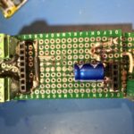
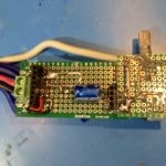
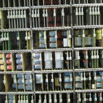
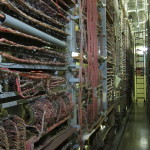
I covered the solder pads on the backs of the amp boards with kapton tape to keep them from shorting on the case. Then I made up a power cable and some speaker cables, screwed them in to the terminals on the motherboard and fed them out of the opening of the case.
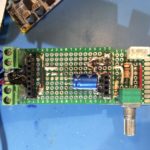
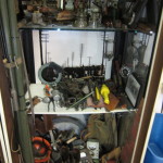
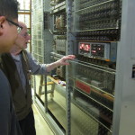
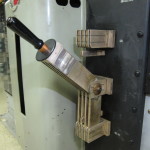
Maneuvering the amp board into the case with all the cables attached took a bit more force than I was hoping for, a situation not helped by the fact that the position I chose for for the audio input connector interfered with part of the case casting, depriving me of a few extra mm at the opposite side of the case, and putting the volume-pot a bit off center.
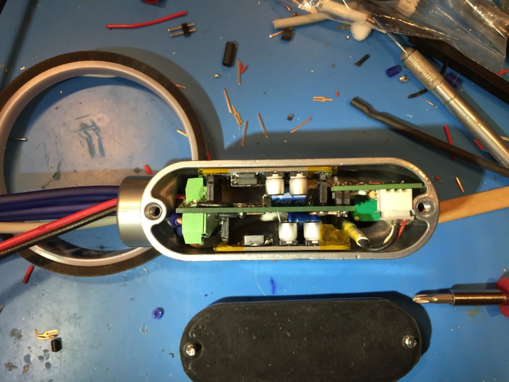
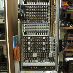
In the end though, I got it to fit.
My plan is to power it off a Quick Charge 2 USB power bank set for 12v output. I have the powerbank, but I still need to make something to negotiate the 12v output, so I powered it off a 12v power brick to test it out.
It works! Even better, it sounds good! So, a second version is a luxury, rather than a necessity. At full volume, the output level with my phone as the audio source is maybe a little lower than I’d like for something intended for use outdoors. I’m not sure yet if that’s a limitation of the 12v supply voltage, or if I need to bump up the gain of the amplifier.
Now that I know it works, I still need to finish it up. I need to fit an extension to the volume potentiometer shaft and pick out a knob that looks good. I also need to put some thermal pads on the bottom of the amp modules to transfer heat to the case. Also I’ll probably find some thinner gauge speaker cable.
Parts Used
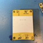
- 2x “Sanwu” (not actually Sanwu branded) TPA3110 30w mono PBTL Class D amplifier board ($2.70 each)
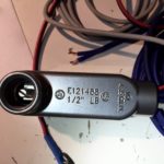
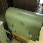
- 1x 1/2″ Rigid Type-LB threaded aluminum conduit body ($3.78)
- 2.54mm pin headers
- 5.08mm two-pin screw terminals (for power-in and speaker outs)
- JST XH-2.54mm 3-pin header (for audio in)
- 1x 20K, linear, stereo potentiometer
- 2.7KOhm resistors
- 22 and 18 AWG solid copper wire
- “zip” wire
- 3.5mm stereo TRS pigtai cable/plugl
- Solder
- Hot Glue
 It is part of a