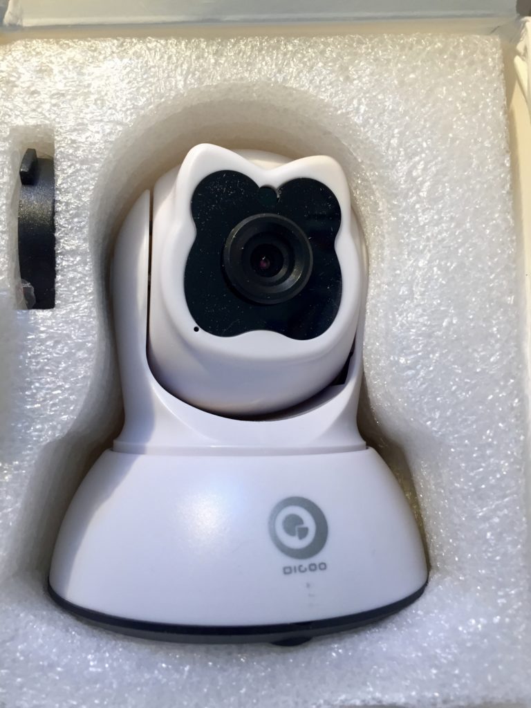
Digoo IP Camera Teardown and Links

I was just looking at unfinished posts and noticed that I’d taken, but not published, a bunch of notes I’d made earlier this year in hopes of hacking better firmware onto the Digoo BB-M2 WiFi PTZ Security Camera.I gave up on the quest, but here are my notes, with minimal editing.

Someone mentioned that the Chinese language page for Netcam360 has a link to the IPC-SDK. When I downloaded it and looked inside, I saw client-side code, but there was also a self-extracting archive called “HSmartLink Win32 SDK” and I remembered the PCB marking started with “HSL.” Searching for HSmartLink brings up hsmartlink.com, which, among other things, has IP webcams! The i9812 looks like a good match for my camera!

Unfortunately, no sign of any firmware updates. I checked the .cn version of the site too. It doesn’t seem as up to date on products (i9812 isn’t listed), and while there is more info in support section, it is still quite sparse. Page that looks like it is intended to link to downloads hasn’t been updated since 2015

Company is “Shenzhen Hsmartlink Technology Co. Ltd”

FCC Database listing for company

So what is the relationship to NetCam360 (check whois & IP ) and they mysterious APKLink?

Nmap Pobe

Starting Nmap 7.40 ( https://nmap.org ) at 2017-02-06 18:38 PST
Nmap scan report for 10.31.1.124
Host is up (0.0043s latency).
Not shown: 998 closed ports
PORT STATE SERVICE
23/tcp open telnet
81/tcp open hosts2-ns
MAC Address: E0:B9:4D:8F:61:6C (Shenzhen Bilian Electronicltd)

Nmap done: 1 IP address (1 host up) scanned in 0.49 seconds

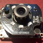
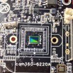
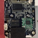
Teardown Inventory

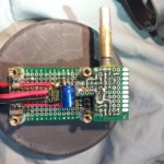
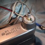
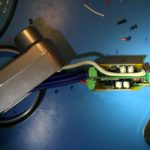
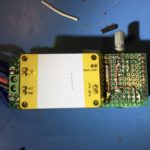
Photos

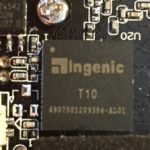
Ingenic

Module with Mediatek MT7601UN

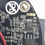
Unknown

  • 15UDN8WY, ULN2803AG 18Pin in 2-row SMD
  • Darlington Transistor Array: http://www.ti.com/lit/ds/symlink/uln2803a.pdf
  • Probably used for driving PT motors

Atmel 542

  • 24C02N, SU27D
  • AT24C02
  • Two-wire serial EEPROM (2K)

Vertical PCB

  • SF1810-002, www.sufeitech.com. PCB antenna?

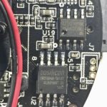
oosilicon or dosilicon?

Other

Balight 21W Folding Solar Panel USB Charger Partial Teardown

I picked up a 21W, 3-panel Balight folding solar panel-based USB charger from Amazon for ~$36 a couple of weeks back. It uses high-efficiency SunPower Maxeon cells much like similar 20-21W panels from AukeyAnker and dozens of obscure brands. All of them have the same basic construction. They are all made from nylon ballistic cloth. Each fold has a panel made from two SunPower cells encapsulated in a flexible waterpoof sheet. The panels provide power via two 5v USB ports, which presumably have some sort of voltage regulator.

I wanted to know more about how the chargers worked. In particular, I wanted to know if they were wired in series, or parallel because I wondered if it was worth trying to tap into the raw output, before the USB regulator to reduce power conversion and resistive losses for some applications.

I thought I’d be able to get the information I needed by finding someone documenting a teardown of their own panel on YouTube or a blog post. Despite the dozens of variants from dozens of brands and a handful of manufactures though, I didn’t find what I was looking for.

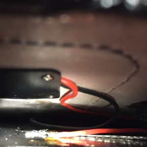
So, I decided to dig up a seam ripper and open my panel far enough to get a look at the wiring, and tap in to it upstream of the voltage regulator.

The panels appear to be wired together with some sort of woven wire conductor. I had some hope that all the cells would be wired in series, to give a nominal panel voltage of 18v. Based on what I could see, and measuring the voltage before the regulator in full sun, it looks like each panel is wired in series, for 6v nominal voltage, and then the panels are wired together in parallel. I was disappointed at first, but this arrangement makes sense in upon further thought.

Using a 2s3p configuration means that the input voltage into the switching regulator should be pretty close to the 5v (actually, 5.2v with enough sun and a light enough load) output of the USB power regulator, which will typically have higher conversion efficiency than 12 or 18 volts. It also means that the manufacturers can stock one converter for everything from a 7W single-panel charger, up to a 28w 4 panel charger without the converter having to support a wide range of input voltages. Perhaps most importantly, it means that partial shading of one panel shouldn’t have a disproportionate impact on the power output of the entire array.

The only downside is that resistive losses in the cabling will be higher with lower voltage and higher current, but that the interconnects aren’t more than a foot or so, the resistive losses shouldn’t be too high.

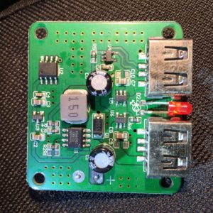
As for the converter itself, I may look at it more closely and add some more details, but, a few initial observations:

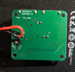
  • The PCB design has extensive ground planes on top and bottom, tied together with vias.
  • Both outputs are served from a single buck-converter (step-down) power supply based on a Techcode TD1583, which is a 380 KHz fixed frequency monolithic step down switch mode regulator with a built in internal Power MOSFET.
  • It looks like only port 1, at the top right in my photo, has the data lines connected, which suggests that it is the only one with fast-charge coding.
  • IC U2 looks like it has its markings sanded off. I notice though that one of its pins is connected to the enable pin on the TD1583, leading me to think that it is responsible for cycling the output to make sure devices draw as much power as possible when the panel voltage rises again after clouds or an object reducing the light falling on the array pass. I don’t know if it is a MCU, some sort of timer, or comparator, or what, though.

There you go. I can’t be sure that other folding solar arrays like this one are wired in the same way, but if they only support a 5v output, I suspect they will be. I hope this proves useful to someone besides me.

Monoprice MP Select Mini v2 Nozzle Replacement

I bought a Monoprice MP Select Mini v2 3D printer in late June. I recently decided I wanted to get some extra nozzles so I could have some spares, I’ve used straight PETG and PLA for most of my prints. I’ve also done some prints with 40% aluminum powder and 60% PLA, have some wood-filled PLA on the way, and I’d like to try printing with a carbon or glass fiber filled plastic too. These composite filaments can all wear the nozzles, hence my need for spares.

Monoprice doesn’t sell replacement nozzles, and nor does anyone else, as far as I can tell.  According the the community-made MP Select Mini wiki, the v1 and v2 use the same nozzle, which has a m6 threaded shaft, is 10mm from end-to-end, and 5m from the tip to the back of the nutted area. That’s what the wiki says, anyway.

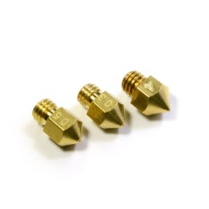
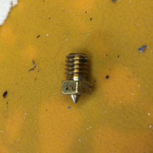
The Wiki didn’t seem right to me. The most obvious issue is that the nozzle shown on the wiki has a different shape, like the photo on the left. There is a conical taper down from the diameter of the integrated nut to the end of the tip. After the nut section, my printer nozzle narrows immediately to ~3.5mm before the conical taper to the tip, like the photo on the right.

A bit of googling didn’t turn up any added details, so I decided to take out my nozzle and measure it with calipers. I pre-heated the hot-end to ~200C, adjusted a crescent wrench and tried unscrewing the nozzle. The whole heater block turned instead, so I grabbed some adjustable pliers, twisted the block back into place, and held it steady while I removed the nozzle.

By my measurements, the overall legnth of the nozzle is 11.5mm. From the back end of the threads to the flange for the nut section is ~6.3mm, and from there to the tip is 5.2.

Now I have to find something that matches those specs…

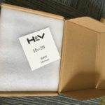
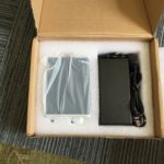
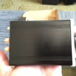
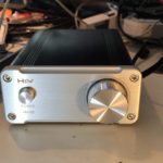
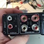
H&V HV-50 TDA7892 50W/channel Class D Amplifier Teardown

I noticed that Banggood just listed the H&V HV-50 TDA 7492 Class-D amp on their site for $59.99 with “Priority Direct” shipping to the US from China. This reminded me that I’ve been remiss in posting anything more about the HV-50 amp I ordered on eBay last summer for ~$35.

After ordering it, I was a bit worried I’d been scammed, because the seller never provided any tracking information, but those fears were quickly laid to rest when it arrived on my doorstep all the way from China in just 9 days!
Sheeny

Some details from my earlier post on the HV-50:

  • 50W per channel (stereo)
  • RCA inputs
  • 5-way binding posts for outputs.
  • Based on the TDA7492 Class D Amplifier IC from ST Microelectronics.
  • Aluminum case.

The TDA7492 chip is used in a lot of compact, inexpensive audio amps made by various Chinese manufacturers and sold under various names on Amazon, Ebay, AliExpress, etc.

One such amp is/was the very similar looking SMSL SA-50 amplifier, which puzzled me, because when I first found the HV-50 listed on AliExpress, the seller listed it as an SMSL product. It wasn’t until I had it in hand that I realized that the eBay listing didn’t mention SMSL and there was actually no reference to SMSL anywhere on the product, or or the very thin users manual.

With some digging though, I found persuasive evidence that H&V is/was a new brand from he same company that produced SMSL. Given the price point, and product photos of the HV-50s internals, which showed signs of cost cutting, I assumed the H&V line would be a new, lower cost line, as SMSL seemed to be moving upmarket. Positioning the HV-50 as a lower cost alternative to SA-50 or A2 amps made sense when the HV-50 sold for $35-40, while the SA-50 & A2 were selling for roughly twice that. It makes less sense with the HV-50 selling for almost $60.

Looking more closely, the SA-50 seems unavailable from Chinese sellers on AliExpress and eBay these days. On Amazon, it sill goes for $60-70. The HV-50 seems to be in the process of being superseded. Aoshida, the source of my original amp seems to have both an eBay and and AliExpress presence. On AliExpress, they have a listing that pictures an HV-50 with a 24v power adapter for $42.28, shipped, but the listing is actually for a “TOE F1 TDA7492 amp” and notes that the housing may say HV-50, but it’s been “upgraded to TOE F1.” Their eBay store has a very similar listing, also for a “TOE F1 TDA7492 amp” for $53.00.

I think the HV-50/TOE F1 is a pretty good deal at $42 shipped with a power brick. At $50-60, that’s less clear. I’d probably pay another $10-15 for an SMSL SA-50. The reason? If the SA-50s shipping today are the same as those shipping a year ago (not a sure thing, given that SMSL changed the guts on the SA-36pro without warning, explanation, or acknowledgement) then they use some high quality film capacitors in key parts of the audio path.

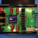
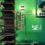
On the other hand, the HV is clearly a cost reduced design, as I suspected from the initial product photos, and confirmed upon receipt. It uses SMD ceramic caps for all but the main power supply caps. I personally think the cheaper caps work well enough. I don’t have an SA-50 to compare the HV-50 to, but while it’s possible they would sound obviously different, I doubt the SA-50 sounds noticeably better. For $30 less than the SA-50, I think the HV-50 is an obvious choice for those on a budget. For the current $10-15, price difference, it is much less clear cut.

What remains to be seen is if the TOE F1 is actually an upgrade, and if so, in what way? Will they adopt the film caps used by the SA-50?

Impressions

When powered up, a tiny click may be emitted from the connected speakers.

I noticed no obvious defects in sound quality. My main complaint is that the design & construction of the PCB-mounted RCA inputs doesn’t make good solid contact with the slotted, machined pins on some higher-quality RCA plugs, leading to noise or audo drop-outs. At first, I though the volume control pot was going bad. I ended up replacing the jacks with some gold-plated panel mount jacks with better design/construction. Interestingly enough, while the original part has trouble with higher-end RCA plugs, it has no problem at all with inexpensive stamped & rolled RCA plugs.

Speaking of connections, the speaker output binding posts are small, but work well with banana plugs, spade connectors and properly trimmed and stripped speaker wire (to avoid shorts).

Caveats

There are a few important caveats about the HV-50, which may or may not apply to the TOE F1:

First, it’s important to understand that the generation of class D amplifier chips like the TDA7492 used in the HV-50, along with the more powerful TDA7498, and the comprable TPA3116, all have consistently inflated power ratings. These ratings are often used in the specs of cheap amps built around such chips.

The inflated ratings aren’t exactly inaccurate, its just that they only apply under unlikely listening conditions. They assume a power supply voltage near the top of their operating range which ends up being 24v for the TDA7492 and TPA3116. This isn’t an issue with the HV-50, which comes with a 24v supply, but can come into play when using ~19-20v laptop adapters. The tests are often performed with ~4 Ohm loads, while lots of home audio speakers are closer to 8 Ohm, and peak power output would be ~50% of the advertised number. The finally issue with the ratings is that they allow up to 10% distortion, a value that most people will find unlistenable. Values are generally also given for up to 1% distortion, which most people will find suitable. The corresponding power ratings are ~50-60% of the advertised value.

In sum then, the usable power of the HV-50 and similar amps with a suitable power supply  is 50W * 50% (for 8Ohm speakers) * 60% (for reasonable distortion levels), which works out to 15w/channel. This may seem much less impressive, but it should be enough power to push most consumer bookshelf speakers close to their (and your) limits.

Second, the HV-50 does not, as claimed in the Bangood listing and elsewhere, contain parts from EPCOS, Philips, ALPS, DALE, etc. The volume control pot seems like a cheap, but adequate generic Chinese part, and the capacitors in the audio path are all SMD ceramics.

Conclusion

Bottom line: The HV-50 is a decent, inexpensive Class D amp if you can get it shipped with PSU for ~$40. Whether it is a good choice vs an SA-50 or similar really depends on the price difference at current market prices.

Photos

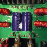
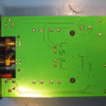
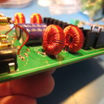
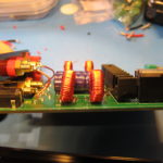
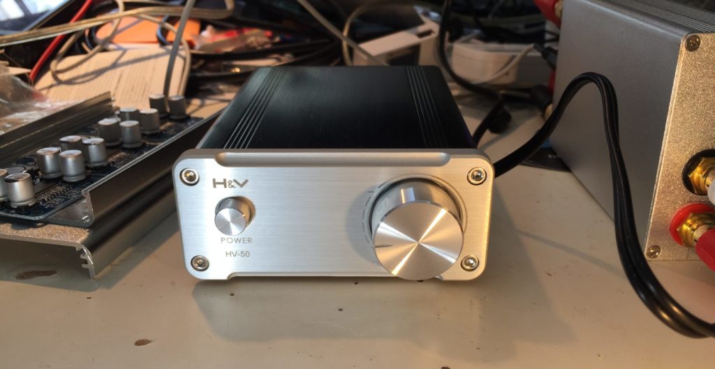
And finally, the main purpose of this post wasn’t writing a wall of text, it was sharing photos of the guts of my HV-50.

Berries, Bananas, Oranges and C.H.I.P.s

I’m in the midst of finding a low-cost embedded linux platform to standardize on for IoT/network device experiments. I’ve been using Debian on Marvel Kirkwood ARM devices as inexpensive, low power servers and network appliances for a number of years now. I’ve also used OpenWRT for my home network and other network appliances.

A few years ago though, I grew tired with the difficulty of maintaining/upgrading Debian on my ARM devices and replaced them with a small AMD based x86 box for my main home server. There have still been upgrade hassles, but overall, I think it reduced the fussyness and frustration enough to be worthwhile.

At about the same time, I started growing interested in using OpenWRT more widely, and I was encouraged when the LEDE Project forked off for reasons that included a desire to fix some of the things that frustrated me about OpenWRT. I liked the simplicity vs a full linux distribution. And the minimal system requirements meant OpenWRT could run on small, inexpensive, relatively low-power devices. Last year, I started work on trying to get OpenWRT running on some cheap linux-based network music servers. Before going further, I paused to think about what’s really important.

I realized that, for my purposes the fact that OpenWRT/LEDE runs on a wide variety of compact, inexpensive devices was as much a liability as an asset. It meant more of the communities effort was invested in supporting the hardware, which meant that a lot of the supported hardware and some of the higher-level software wasn’t well supported, or supported at all. Furthermore, the constrained resources on the various hardware made it harder to compile, package, and deploy software packages that were well supported on full linux distributions. These tradeoffs between cost and ease of development/deployment might be acceptable if I was working on a high-volume device, but I’m not. I’m working on one-offs for my own projects. At most, I might make/deploy a dozen similar devices. How much hassle was I inflicting on myself in exchange for saving $20, or $200 vs an easier to use alternative?

As for the alternative, figuring that out is really the point of this post. As I see it, there are three major options.

  • RaspberryPi
  • Chinese ARM (Allwinner, Rockchip, Amlogic, etc)
  • NextThing

And my current impressions on each option:

RaspberryPi

Anyone who has read this far is probably well aware of the success of the RaspberryPi and its offspring, like the RPi Zero and RaspberryPi v3. Community support is surely the strongest out of any of the inexpensive ARM boards. Unfortunately, I don’t find the boards a great fit for most of my projects.

The Raspberry Pi v3 is quite capable in terms of processing and video. Of those the processing power is probably the most relevant to me, but the projects that call for that also call for better network and disk IO, rather than the shared USB2 on the v3. Also, at $35-40 it’s more expensive than I’d like. It’s a bit on the large size too, and power consumption can be a bit high.

The RPi Zero is cheap ~$5 but availability has been poor, and it still seems hard to get. It’s small, and power consumption is better than the v3. Unfortunately, the Zero seems targeted at people who want to do more hardware hacking than I do. IO is minimal. There is no network, and no included support for USB peripherals (it can be a USB peripheral though).

It’s been almost a year since these two devices were released, so there is a good chance we’ll be seeing upgrades soon. Still, I’m not holding my breath.

Chinese ARM Boards ( with SoCs from Allwinner, Rockchip, etc ).

If I remember right, ARM SoCs from Allwinner and Rockchip first appeared at about the same time as the first RaspberryPi, in android TV boxes and sticks. The first developer board I remember was the Allwinner-based Cubieboard. Since then, there have been many variants from a half-dozen board designers like FriendlyARM, (SinoVOIP) Bannana Pi, (Xunlong) Orange Pi.

Unfortunately Allwinner, and most/all of the other SoC makers aren’t great about providing documentation or source code for their linux variants, and the board makers don’t/can’t exert much leverage. Allwinner chips seem to have a decent community around them, but there are so many SoC variants and board variants that a lot of effort is burned trying to keep up with them. The linux-sunixi (Allwinner) community is making a concerted effort at getting support into the mainline linux kernel, which should both make ongoing support easier and broaden the base of potential contributors.

Next Thing C.H.I.P.

Next Thing grabbed a lot of attention in late 2015 for their promise of a $9 computer called the C.H.I.P. After some challenges, they delivered on their Kickstarter and went on to produce more of the boards, as well as the PocketCHIP and upcoming CHIP Pro.

The C.H.I.P. includes 4GB of fast onboard flash, 2.4GHz 802.11n WiFi, Bluetooth 4.0,  512MB RAM and multi-format video out (built-in composite, or VGA & HDMI with adapters).

NextThing used yet another Allwinner ARM SoC (R8), and by that criteria, belong in the previous category. What sets them apart from other people spinning boards with cheap ARM SoCs is that they have invested time and money into software and documentation — including a full datasheet for the GR8 (R8 + 256MG RAM in package) used on their C.H.I.P. Pro.

They are currently out of stock on the CHIP and all they can say about backorders is that they are expected to ship in Q1 2017.

Conclusions

I already have an RPi v3, which I’ll find some semi-permenant use for. the C.H.I.P. is attractive because of it’s manufacturer support, despite being out of stock, and having an older Cortex-A8 CPU core. I’m not in a huge hurry, so I think I’ll order a couple now and hope they arrive before I wish they were here sooner.

I’m also tempted to buy an Orange Pi Zero, or one of the FriendlyARM NanoPi variants, for comparison.

The Conduit Amplifier r2

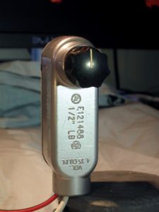
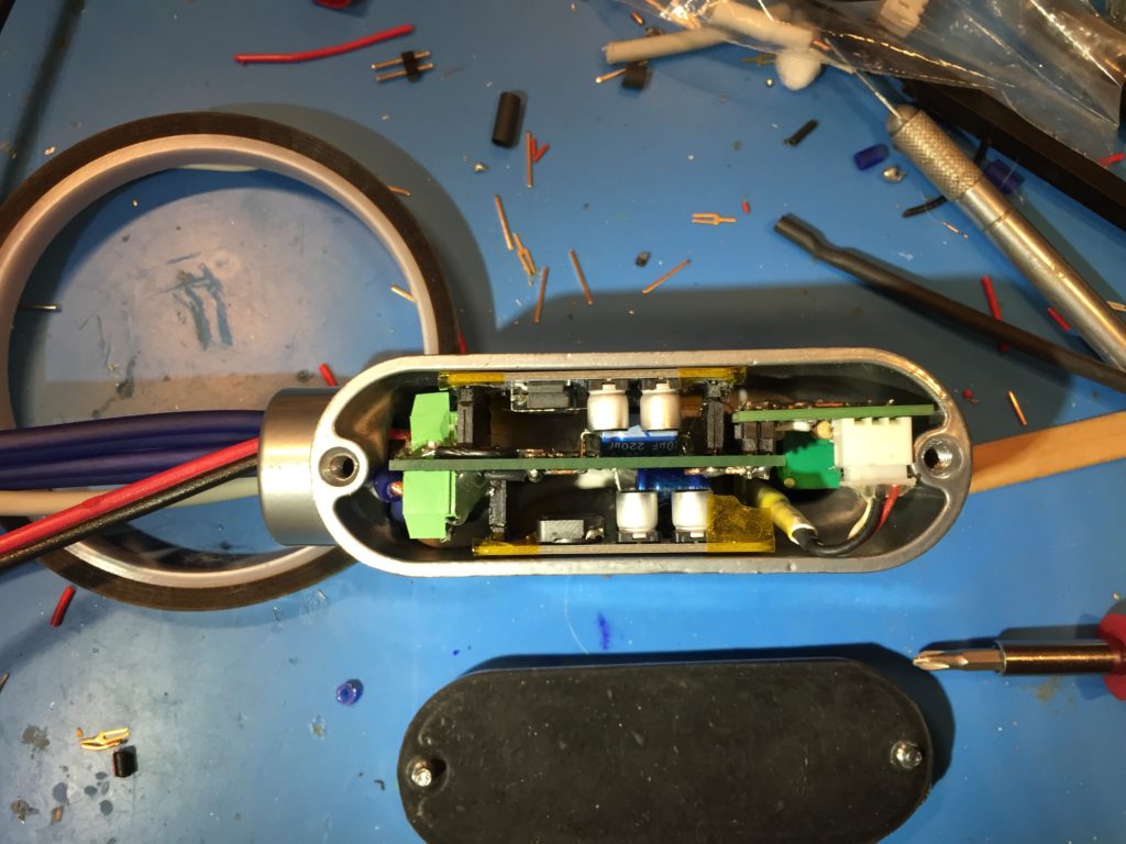
I made a major revision to my Conduit amp in order to free some internal space to ease cabling.IMG_8270

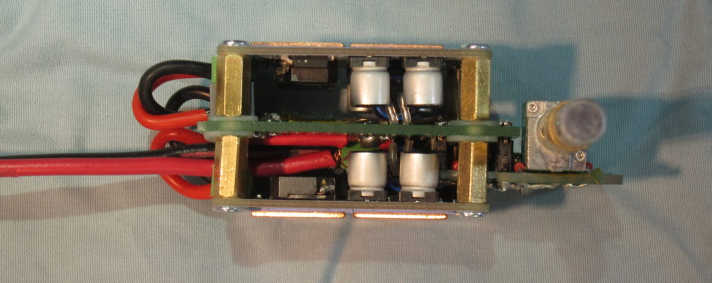
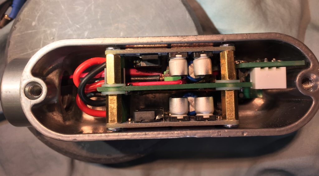
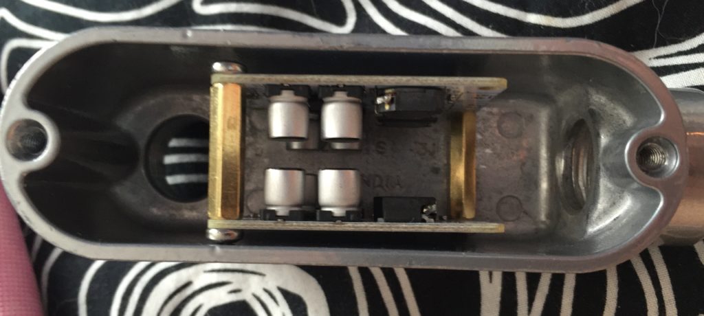
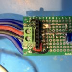
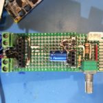
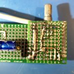
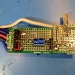
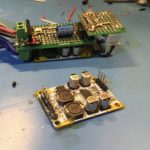
The original version used pin-headers on the mono TPA3110 amplifier modules to connect them to a perfboard motherboard. Connectors for power input and speaker output terminals were on the motherbnoard. The new version uses smaller screw terminals, and moves the speaker output terminals to the amp modules, which are held in place by sandoffs. Pin headers are still used for audio inputs to the modules, and power is still connected to the motherboard, and then supplied to screw terminals on the modules via 18 gauge silicone wire. I also managed a more compact layout for the volume control daughter board.

IMG_8233

The new version also included improved fit-and-finish to the volume control. I used some aluminum rod and brass tubing to make an extension. This now passes through a drilled-out aluminum plug before being connected to the knob. I’d originally intended to fit a bearing in the plug to support the shaft, but I don’t have one in the proper size (even so, after adjustment shaft alignment is better than pictured).

IMG_0415

I also fitted the thermal pad and copper shims to thermally couple the amp modules to the aluminum case.

Unfortunately, only one channel works. I checked for continuity and power before noticing that a small SMD cap near the PTA3110 chip on the amp board got knocked loose. I’ll have to figure out its specs and try to get and fit a replacement… though it would be easier to just replace the board for $2.50.

I think its a nice improvement. I still need to get wire and connectors I’m happy with the power, speaker, and audio pigtails. Someone suggested 4-pole speakon connectors for the speakers. There is an aluminum version that might be a good match for the case, except it costs about as much as all the other parts combined. There are cheaper plastic speakon connectors that I might try. I’d also like to find a decent pot with an integrated switch I can use to switch the power.

The Conduit: A portable, Class D TPA3110 Audio Amplifier

Update: I made a major revision to The Conduit Amp with some improvements and a bit better fit and finish.

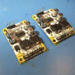
A few months ago I was at the hardware store looking for cheap enclosures for electronics projects. Some aluminum junction boxes for electrical conduit caught my eye, so I bought a couple. In parallel, I was interested in building a small, portable amp that could operate off 12v, which led me to buy some little, mono, TPA3110 modules for a few bucks each.

Surveying my box of parts a couple weeks ago, I noticed that the TPA3110 modules would fit nicely in the smaller of the two junction boxes I purchased, and I started tinkering with ways to assemble them into a finished product.

IMG_0239

The first idea was to join the boards together with standoffs and slip them inside. I ordered some small terminal blocks for the electrical connections. When they came, though, and I tried assembling things as I planned, I realized I’d need to cut the standoffs down in order to fit a board to hold a potentiometer. I was feeling lazy, and didn’t want to deal with metal filings, so I looked for another way.

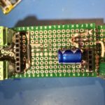
I decided to use pin-headers to mate the amp modules with small motherboard made from perfboard. For added mechanical strength, I cut the headers with more pins than needed, soldered the pin positions with through-holes on the amp board, and then glued the rest and trimmed them to the same length as the active pins.

Routing the power input and speaker outputs was kind of a nightmare. Rather than trying to plan it all out, I ended up working a couple of connections at once, trying to leave room for the other connections. It took quite a while. I was concerned about some of the routing and figured I’d probably end up doing a second version, so I soldiered on soldering my prototype.

Once I was done, I used my multimeter to check to make sure that there weren’t any short circuits on the motherboard. Fortunately, everything checked out.

Next I had to finish up the input connections and passive volume control. Rather than routing the audio input on the protoboard, I decided to take advantage of the shielding on the input to help keep the signal clean while passing the high-current power and output connections, and the inductors on the amp board. I connected it to the board with the volume-control board at the far end of the case.

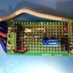
After assembling the components on the volume control board I checked everything with a multimeter. Again, I was fortunate that I hadn’t ended up with any shorts. The volume control board was connected to the the “motherboard” with an excess of soldered pin headers for mechanical stability.

I covered the solder pads on the backs of the amp boards with kapton tape to keep them from shorting on the case. Then I made up a power cable and some speaker cables, screwed them in to the terminals on the motherboard and fed them out of the opening of the case.

Maneuvering the amp board into the case with all the cables attached took a bit more force than I was hoping for, a situation not helped by the fact that the position I chose for for the audio input connector interfered with part of the case casting, depriving me of a few extra mm at the opposite side of the case, and putting the volume-pot a bit off center.

IMG_0317

In the end though, I got it to fit.

My plan is to power it off a Quick Charge 2 USB power bank set for 12v output. I have the powerbank, but I still need to make something to negotiate the 12v output, so I powered it off a 12v power brick to test it out.

It works! Even better, it sounds good! So, a second version is a luxury, rather than a necessity. At full volume, the output level with my phone as the audio source is maybe a little lower than I’d like for something intended for use outdoors. I’m not sure yet if that’s a limitation of the 12v supply voltage, or if I need to bump up the gain of the amplifier.

Now that I know it works, I still need to finish it up. I need to fit an extension to the volume potentiometer shaft and pick out a knob that looks good. I also need to put some thermal pads on the bottom of the amp modules to transfer heat to the case. Also I’ll probably find some thinner gauge speaker cable.

Parts Used

Power Rail Noise/Ripple with a Sanwu Blue TPA3118 Mono Class D Amplifier Module

I’m building a few custom audio amplifiers for my personal use out of some inexpensive modules based on the Texas Instruments TPA3118 and TPA3116 Class D amplifier chips.

Class D amplifiers are basically variable switching regulated power supplies (SMPS), which makes them compact and power efficient when compared to traditional amplifiers, which are much more like linear regulated power supplies. The switching frequencies are designed to be well outside of the range of human hearing (and the circuits and transducers we use to reproduce sound) so that it can be filtered without interfering with the audio, and so any remaining signal at switching frequencies is inaudible. In the case of the modules I’m using, the switching frequency is ~400KHz.

The modules I am using have LC (inductor + capacitor) filters on their outputs in order to filter the switching frequency before sending it to the speakers, but I was concerned that the modules would also inject noise onto the power supply rails. TI has provisions for slaving multiple chips together so that they use the same switching clock and can avoid distortion due to interactions on the power supply bus, but the modules I’m using don’t expose the necessary pins, and the small component sizes and spacing between the PCB traces didn’t make me eager to hack them.

Some people have addressed the issue by dedicating a separate power supply to each module, but all things being equal, using a single supply should be cheaper and more compact. I asked for advice on the DIYAudio.com forum, and got some general suggestions, but nothing specific enough to be actionable. I was going to need to do more of the legwork myself.

So, first step, was to see if there were any existing solutions. I started reading datasheets and application notes, but I didn’t find what I thought I needed. I did learn though that, in addition to the switching frequency, Class D amps draw current at either 1x the audio input frequencies, when configured as a half-bridge, or 2x the audio input frequency, when configured as a full bridge.

Next step was to measure magnitude of these potential PSU noise sources in a naive implementation, with no added filtering beyond the PSU’s output filters and the modules PSU input filters.

I used the 24v DC PSU I had handy, an ~10-12 year old 65W Apple 24V PSU intended for a Macintosh PowerBook. I haven’t seen a teardown of the PSU, but in general, Apple seems to put a lot of effort into making their PSUs electrically robust and low noise.

I paired this with a Sanwu “Blue” TPA3118 PBTL mono module. which has ~1320uF (2x 2x 330uF) of electrolytic decoupling caps on the power rails. I then hooked up my oscilloscope and an Analog Discovery to do the measurements.

DS1Z_QuickPrint2

With no signal input to the amp, this is what the power supply rail (yellow) and the amp output (blue) look like. You can see that there is a sinuous ~400KHz, 1.2v peak-to-peak signal on the output from idle switching of the output bridge. You can also see evidence of this switching on the power rail, at the same fundamental frequency, but with a lot of ringing. The 400KHz component is about 50mV peak-to-peak, while the higher-frequency ringing and transients are about 190mV p-p.
I also took measurements using my Analog Discovery as a spectrum analyzer.

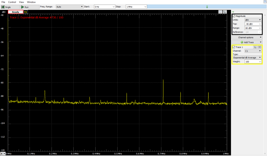
Baseline 1MHz Narrower Y range (similar lashup, no AC power to PSU)

First with everything connected, but no AC power applied to the PSU.

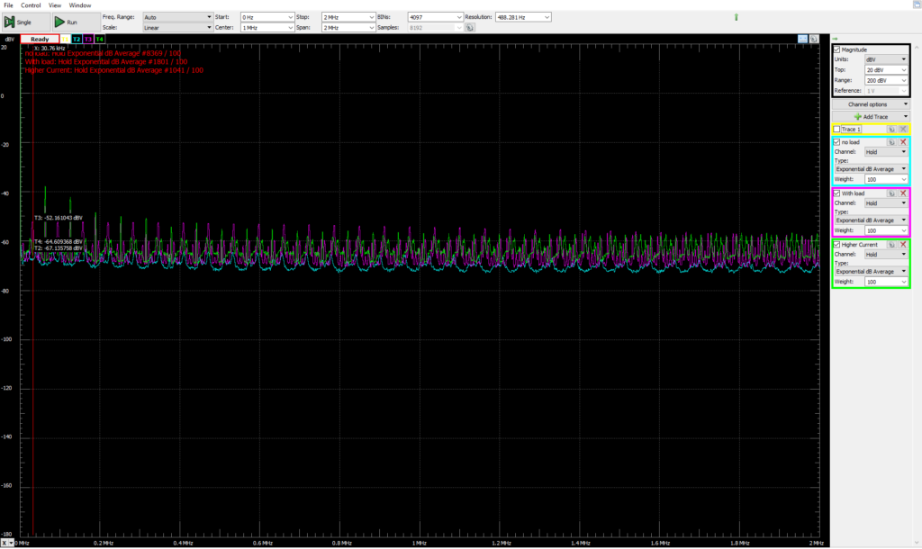
Apple 24v Brick with resistor load

Next, with AC power, and various resistive loads. I was sloppy and didn’t record the exact condutions, but it gives some sense of what the PSU noise is and how it changes with load. Blue is with no load, magenta is with ~30 Ohms, Green is with ~15 Ohms. Also, note, this is a relatively wide spectrum range, from ~0 to 2MHz.

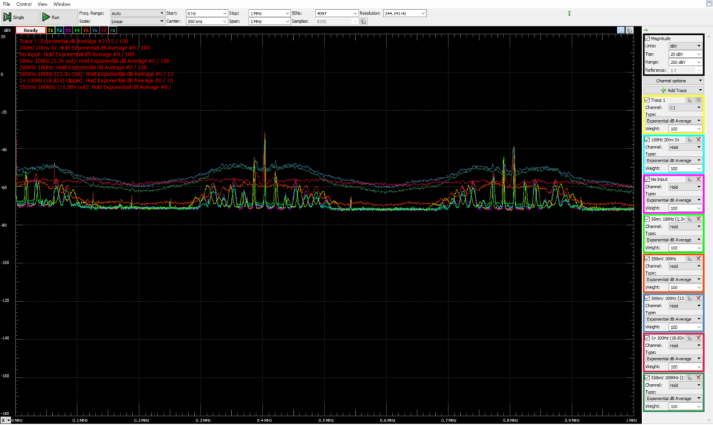
0-1v 100Hz in. multiple traces. 1MHz wide

With the amp as a load (driving a 7.5Ohm power resistor). There is a 100Hz input to the amp. Each trace is a spectrum measurement of the PSU with a different input amplitude, from signal-off to 1v peak-to-peak. These readings were DC coupled, so the measurement reflects the DC voltage component. As a result, the average level for each trace is closer to the baseline as the DC voltage of the PSU rails sags at higher output powers.

There are peaks at the 400KHz switching frequency, and its harmonic at 800KHz. I’m not sure I understand all the little peaks that group around on each side of the switching frequency.

DS1Z_QuickPrint3

In the time domain, we can see the amplifier-induced PSU ripple & noise in the yellow trace, along with the amplifier output signal from a 500mv p-p, 100Hz input signal. There is a 200Hz ripple on the power supply rail as the amplifier bridge switches on 2x for each input cycle, once to drive the output high, and then again, in reverse polarity, to drive the output low. This ripple is ~500-600mV p-p and its phase is offset a bit from the output waveform. On top of that, you can see the switching noise in the high-frequency “fuzz” on the power supply rail. This “fuzz” is about 1.3v P2P. The two components together add up to ~1.96v of swing.
DS1Z_QuickPrint4

Pushing the input higher quickly runs into problems. With 1v input p-p, things look rather nasty as the peaks get brutally clipped off against the limits of the PSU voltage.
I also took PSU rail frequency measurements with input signals of 50Hz and 10KHz.

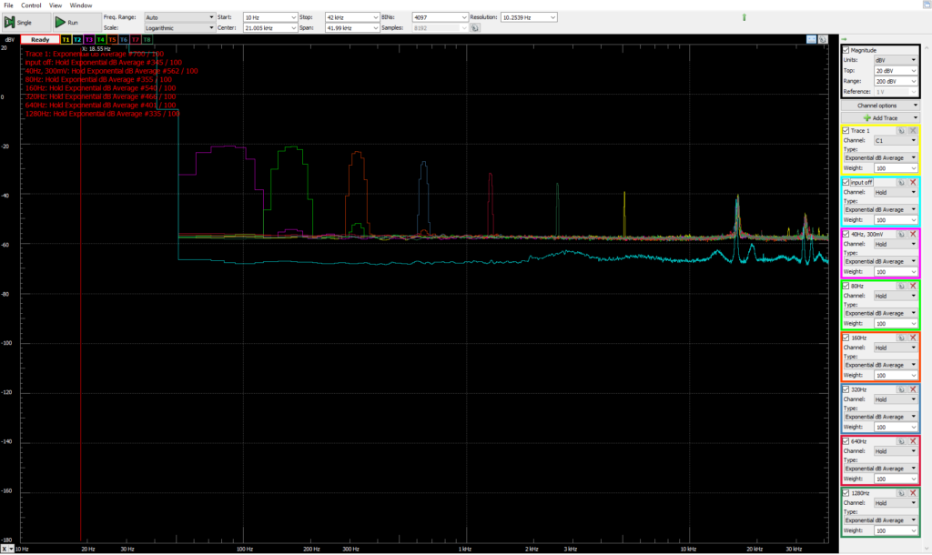
40-1280Hz 300mV in

I decided to wrap things up by looking more closely at the impact on PSU voltage at different input audio frequencies. Since the human hearing falls off sharply above 20KHz, and the amp current draw varies at 2x the input frequency, I limited the top of the measurement range to 42KHz. The input signal was 300mv peak-to-peak, and the input frequency was stepped starting at 40Hz and ending at 1,280Hz.

I’m really not sure what the high-frequency peaks are starting at 18KHz or so. I probably should have looked into them more closely.

Now that I have the measurements, I have to make sure I actually understand them before I figure out what to do, and how to do it. I note that in PBTL mode, the chip has a power supply ripple rejection ratio of 75-80dB up to 1KHz, rising to ~55dB at 8KHz and continuing at that level for the rest of the audio range.


Mac OS X Kernel Panics with RTL-SDR/RTL2832U and Analog Discovery, and a Fix

Earlier this week I fired up WaveForms in order to do some spectrum analysis of power supply rails hooked up to a Class D amplifier board using my Analog Discovery. Before I got the Analog Discovery plugged in though, my computer froze, the screen went dark, and then a kernel panic error displayed.

This was new, I’ve never had a problem before, whether or not the device was hooked up before firing up the software. I tried again, this time making sure the Analog Discovery was plugged in before launching Waveforms. Another kernel panic. I tried again, this time plugging it directly into my laptop, rather than the USB3 hub I use for convenience. Another kernel panic. I muttered and cursed and speculated that the cause was the OS X 10.11.6 update I’d recently installed, and ended up using a Windows machine for the task instead.

A few days later, I received a cheap RTL2832 USB DVB receiver I’d purchased in order to (finally) experiment with Software Defined Radio (SDR) using RTL-SDR software. My first explorations were tacked from base camps on my patio and bed. Everything worked without issue. The third time though, I was at my desk, and as soon as I launched CubicSDR my computer froze, went black, and then complained of a kernel panic.

I was peeved. I thought, perhaps that my hub was an issue, so I plugged the RTL2832 in directly. It worked. I tried a different hub. It worked again. I tried something else, it crashed.

Eventually, I figured out that the problem only occurs with a USB3 to Gigabit Ethernet adapter connected (with or without a hub involved). The adapter in question is based on the RTL8153 chip, which is used in USB3 to GigE adapters sold under many different names.

This chip is complaint with standard USB Ethernet protocols, and works with generic drivers provided by Apple in OS X 10.11 (El Capitan), and perhaps earlier versions. I’d installed the Realtek provided driver in order to take advantage of some features of the chip which might improve performance and power consumption, but not to a significant degree.

By removing the Realtek RTL8153 driver using a script provided in the installer package, I was able to revert to using the generic apple USB Ethernet driver. Now, I can use my Analog Discovery with Waveforms, my RTL-SDR with CubicSDR, and my USB3 Ethernet adapter at the same time without Kernel panics.