Apple Music Lossless and AirPlay don’t Work Like You Think They Should

UPDATE June 23, 2021: My testing, below, was done on MacOS. There is evidence that the iOS version of Apple Music behaves differently with AirPlay v1 receivers. I will investigate further as time and ability permits.

June 25, 2021: More information that adds to the picture on iOS. It looks like AppleMusic on iOS and MacOS use AAC when the apps is set to use an AirPlay 2 receiver for output. However, when the output is an AirPlay v1 receiver, the iOS version apparently maintains a lossless chain from Apple’s servers through to the AirPlay receiver (MacOS switches to stream an AAC version from Apple’s servers and then uses ALAC to transport that over the LAN)

Earlier this month Apple released an update to Apple Music that allows “lossless” streaming in addition to the previous high-quality AAC compressed version. People assumed that they’d be able to play back these lossless streams losslessly over AirPlay because AirPlay uses lossless ALAC (Apple Lossless Audio Codec) to transport audio. Unfortunately, this isn’t true.

What is true:

Apple Music on MacOS does not transfer lossless data over to AirPlay 2 receivers when playing Apple Music lossless tracks. The situation on iOS is unclear at this point.

  • Apple doesn’t say anything about AirPlay on their Apple Music Lossless support page (as of 2021-06-17). They do say that HomePods, which are AirPlay 2 receivers, only support AAC playback at this time.
  • An AirPlay 2 licensee reports that Apple Music sends an AAC stream to their devices when playing back Apple Music Lossless tracks, despite device support for ALAC. Their example suggests they were using an iPad to send the stream to their AirPlay 2 receiver.
  • When playing an Apple Music Lossless track on MacOS to an AirPort Express v2 the lossless icon is displayed. The data rate between my computer and the Airport Express v2, which supports AirPlay 2, averages out to be about 256kbps (delivered in bursts), rather than the steady 800-1000kbps I see when playing an ALAC rip I made of a CD.
  • Apple does use ALAC when playing to an original AirPort Express over the original AirPlay (which is all the hardware supports). This is evidenced by the steady 800-1000kbps data stream between my computer and the AirPort Express. However, in this case, Apple Music reports that the track being played is in AAC format.
  • The Wikipedia page on AirPlay is out of date.

There is no reason to think it works any differently on iOS devices, particularly since the AAC support was probably added, in part, to reduce power consumption on battery powered devices. AirPlay 2 added support for a variety of codecs, bit-depths and sample rates, in addition to the ALAC used by the original AirPlay/AirTunes protocol.

For some reason they seem to be bending over backwards to avoid an unbroken lossless chain between Apple Music’s servers and AirPlay (v1 and v2) receivers. We’ll see if this changes.

Background

AirPlay, or AirTunes, as it was then called, originally only supported lossless transmission using the ALAC codec when it debuted in 2004 alongside the original AirPort Express. This remained true when Apple released the upgraded AirPort Express v2. Along the way Apple also added AirPlay support to the Apple TV along with licensing the technology to 3rd parties to incorporate into devices like AV receivers. People also cracked the encryption used by AirPlay and reverse-engineered the protocol leading to software like shairport-sync which has been incorporated into various commercial and open source products.

Then, in 2018 Apple released AirPlay 2 alongside the new HomePod smart speaker. They upgraded Apple TV to support AirPlay 2, and, to people’s pleasant surprise, also released an firmware update for the long discontinued AirPort Express 2 that added AirPlay 2 support. The new protocol was also licensed to 3rd parties for incorporation in their products.

AirPlay 2 enabled multi-room playback over AirPlay from iOS devices; they’d previously only been able to play to a single AirPlay endpoint at a time. Related to that, AirPlay 2 allowed multiple HomePod speakers to be used as stereo or surround-sound speakers. People assumed that this new functionality continued to use the lossless ALAC codec for transferring audio data between the Mac or iOS device and an AirPlay 2 receiver. The truth was more complicated.

In order to support the new use cases mentioned above, AirPlay 2 included some significant changes. First, it added a buffered mode that allowed a significant amount of data to be stored in RAM on the AirPlay 2 receiver device, rather than streaming it in realtime. More significantly, they added support for other codecs, sample depths and sample rates besides the 16-bit, 44.1kHz ALAC used by AirPlay 2. One of those new combinations was the high-quality but lossy 256kbps AAC that Apple used for iTunes downloads. Many of these details are documented by people working to reverse-engineer AirPlay 2. Combined, these changes reduced power consumption for mobile devices and allowed more headroom to avoid glitches when playing to multiple AirPlay 2 receivers at once.

When Apple announced that Apple Music would support CD-quality lossless audio, people (including me) assumed that it would work with AirPlay devices because they too supported CD-quality lossless audio. However, as I detailed above, this has proven not to be the case.

It seems like Apple has gone to some effort in order to avoid an unbroken chain of lossless audio from Apple’s servers to AirPlay 2 receivers. I speculate they may doing this to keep people from downloading and distributing high-quality lossless content by way of the already cracked AirPlay v1 protocol, or an eventual compromise of AirPlay v2. Given this, I wonder if we’ll ever get the fully lossless signal chain we want over AirPlay, at least not without a new version of the protocol, a change that may require a “forklift” upgrade of AirPlay receivers to take advantage of.

Or maybe it’s all a bug. Apple Music’s Lossless and Atmos roll-out certainly has come with plenty of other glitches and blunders.

Footnotes

  • I’ve only focused on the evolution of AirPlay audio support; It also has support for photos, video and display extension/mirroring.
  • On a Mac, if you choose “Computer” as the output in Apple Music and then choose an AirPlay (v1 or v2) device as your output from the MacOS “sound” menu it will use a lossless signal chain, but it will run the output through the system mixer (so system sounds like alerts will come out the AirPlay receiver).
H&V HV-50 TDA7892 50W/channel Class D Amplifier Teardown

I noticed that Banggood just listed the H&V HV-50 TDA 7492 Class-D amp on their site for $59.99 with “Priority Direct” shipping to the US from China. This reminded me that I’ve been remiss in posting anything more about the HV-50 amp I ordered on eBay last summer for ~$35.

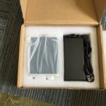
After ordering it, I was a bit worried I’d been scammed, because the seller never provided any tracking information, but those fears were quickly laid to rest when it arrived on my doorstep all the way from China in just 9 days!

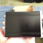
Sheeny

Some details from my earlier post on the HV-50:

  • 50W per channel (stereo)
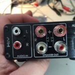
  • RCA inputs
  • 5-way binding posts for outputs.
  • Based on the TDA7492 Class D Amplifier IC from ST Microelectronics.
  • Aluminum case.

The TDA7492 chip is used in a lot of compact, inexpensive audio amps made by various Chinese manufacturers and sold under various names on Amazon, Ebay, AliExpress, etc.

One such amp is/was the very similar looking SMSL SA-50 amplifier, which puzzled me, because when I first found the HV-50 listed on AliExpress, the seller listed it as an SMSL product. It wasn’t until I had it in hand that I realized that the eBay listing didn’t mention SMSL and there was actually no reference to SMSL anywhere on the product, or or the very thin users manual.

With some digging though, I found persuasive evidence that H&V is/was a new brand from he same company that produced SMSL. Given the price point, and product photos of the HV-50s internals, which showed signs of cost cutting, I assumed the H&V line would be a new, lower cost line, as SMSL seemed to be moving upmarket. Positioning the HV-50 as a lower cost alternative to SA-50 or A2 amps made sense when the HV-50 sold for $35-40, while the SA-50 & A2 were selling for roughly twice that. It makes less sense with the HV-50 selling for almost $60.

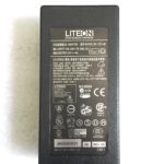
Looking more closely, the SA-50 seems unavailable from Chinese sellers on AliExpress and eBay these days. On Amazon, it sill goes for $60-70. The HV-50 seems to be in the process of being superseded. Aoshida, the source of my original amp seems to have both an eBay and and AliExpress presence. On AliExpress, they have a listing that pictures an HV-50 with a 24v power adapter for $42.28, shipped, but the listing is actually for a “TOE F1 TDA7492 amp” and notes that the housing may say HV-50, but it’s been “upgraded to TOE F1.” Their eBay store has a very similar listing, also for a “TOE F1 TDA7492 amp” for $53.00.

I think the HV-50/TOE F1 is a pretty good deal at $42 shipped with a power brick. At $50-60, that’s less clear. I’d probably pay another $10-15 for an SMSL SA-50. The reason? If the SA-50s shipping today are the same as those shipping a year ago (not a sure thing, given that SMSL changed the guts on the SA-36pro without warning, explanation, or acknowledgement) then they use some high quality film capacitors in key parts of the audio path.

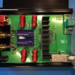
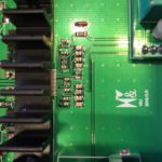
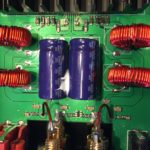
On the other hand, the HV is clearly a cost reduced design, as I suspected from the initial product photos, and confirmed upon receipt. It uses SMD ceramic caps for all but the main power supply caps. I personally think the cheaper caps work well enough. I don’t have an SA-50 to compare the HV-50 to, but while it’s possible they would sound obviously different, I doubt the SA-50 sounds noticeably better. For $30 less than the SA-50, I think the HV-50 is an obvious choice for those on a budget. For the current $10-15, price difference, it is much less clear cut.

What remains to be seen is if the TOE F1 is actually an upgrade, and if so, in what way? Will they adopt the film caps used by the SA-50?

Impressions

When powered up, a tiny click may be emitted from the connected speakers.

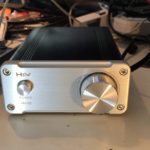
I noticed no obvious defects in sound quality. My main complaint is that the design & construction of the PCB-mounted RCA inputs doesn’t make good solid contact with the slotted, machined pins on some higher-quality RCA plugs, leading to noise or audo drop-outs. At first, I though the volume control pot was going bad. I ended up replacing the jacks with some gold-plated panel mount jacks with better design/construction. Interestingly enough, while the original part has trouble with higher-end RCA plugs, it has no problem at all with inexpensive stamped & rolled RCA plugs.

Speaking of connections, the speaker output binding posts are small, but work well with banana plugs, spade connectors and properly trimmed and stripped speaker wire (to avoid shorts).

Caveats

There are a few important caveats about the HV-50, which may or may not apply to the TOE F1:

First, it’s important to understand that the generation of class D amplifier chips like the TDA7492 used in the HV-50, along with the more powerful TDA7498, and the comprable TPA3116, all have consistently inflated power ratings. These ratings are often used in the specs of cheap amps built around such chips.

The inflated ratings aren’t exactly inaccurate, its just that they only apply under unlikely listening conditions. They assume a power supply voltage near the top of their operating range which ends up being 24v for the TDA7492 and TPA3116. This isn’t an issue with the HV-50, which comes with a 24v supply, but can come into play when using ~19-20v laptop adapters. The tests are often performed with ~4 Ohm loads, while lots of home audio speakers are closer to 8 Ohm, and peak power output would be ~50% of the advertised number. The finally issue with the ratings is that they allow up to 10% distortion, a value that most people will find unlistenable. Values are generally also given for up to 1% distortion, which most people will find suitable. The corresponding power ratings are ~50-60% of the advertised value.

In sum then, the usable power of the HV-50 and similar amps with a suitable power supply  is 50W * 50% (for 8Ohm speakers) * 60% (for reasonable distortion levels), which works out to 15w/channel. This may seem much less impressive, but it should be enough power to push most consumer bookshelf speakers close to their (and your) limits.

Second, the HV-50 does not, as claimed in the Bangood listing and elsewhere, contain parts from EPCOS, Philips, ALPS, DALE, etc. The volume control pot seems like a cheap, but adequate generic Chinese part, and the capacitors in the audio path are all SMD ceramics.

Conclusion

Bottom line: The HV-50 is a decent, inexpensive Class D amp if you can get it shipped with PSU for ~$40. Whether it is a good choice vs an SA-50 or similar really depends on the price difference at current market prices.

Photos

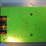
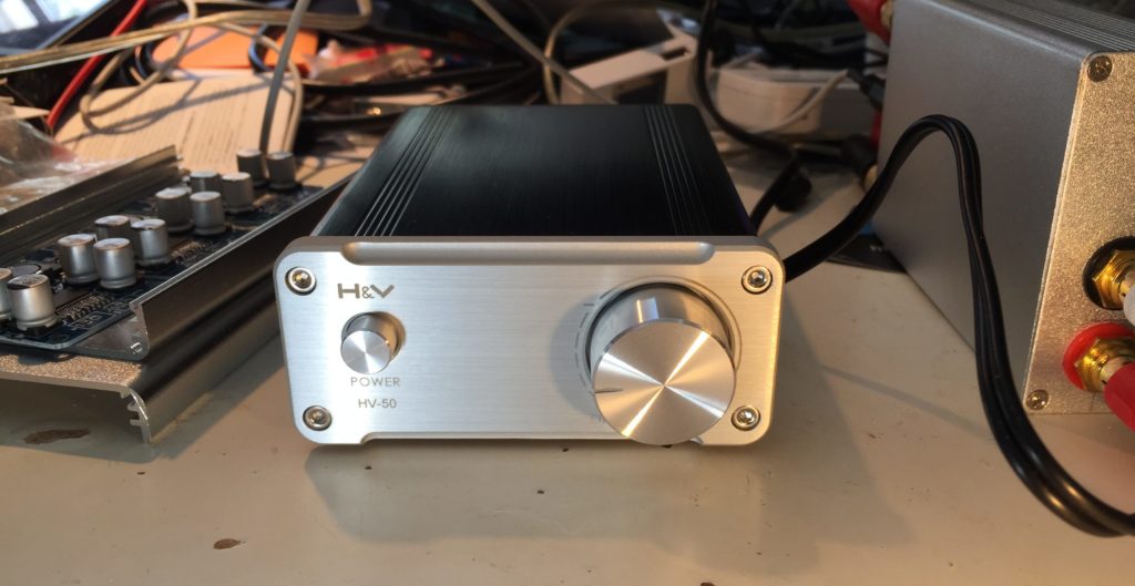
And finally, the main purpose of this post wasn’t writing a wall of text, it was sharing photos of the guts of my HV-50.

The Conduit Amplifier r2

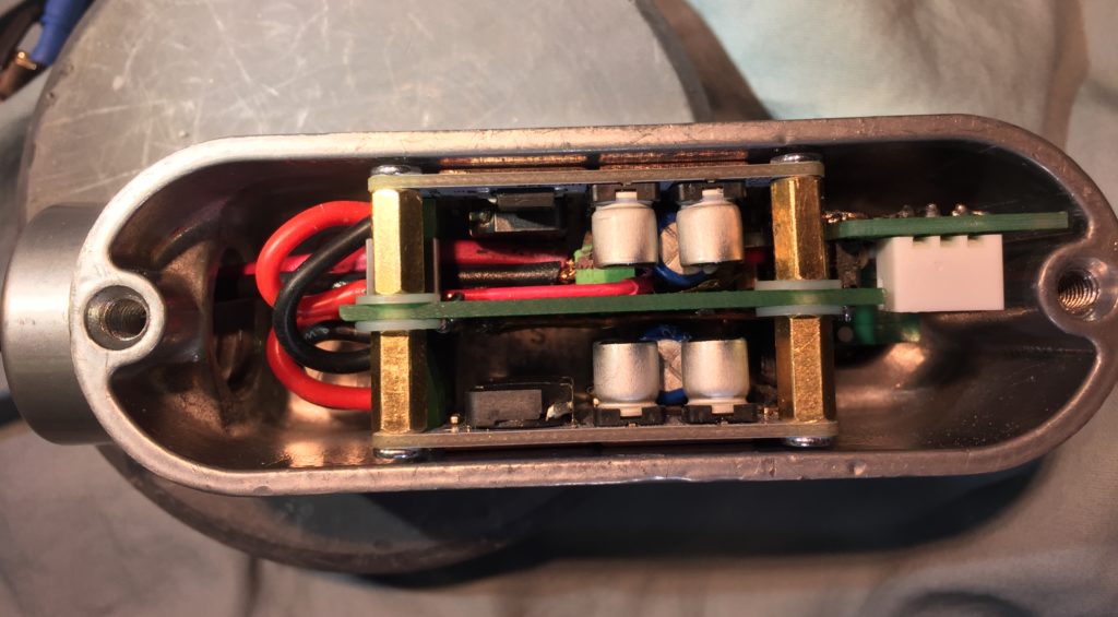
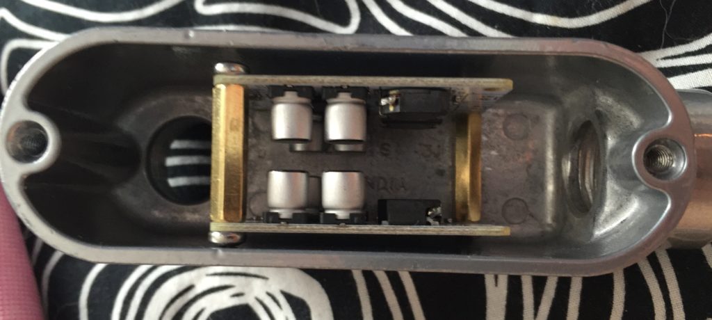
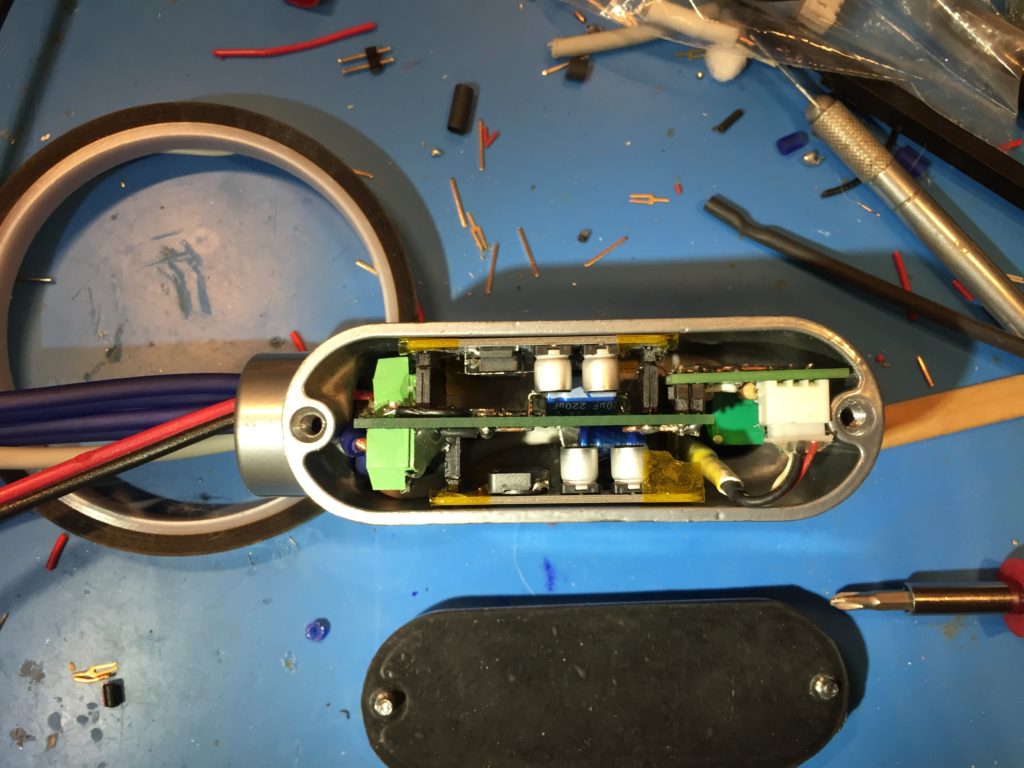
I made a major revision to my Conduit amp in order to free some internal space to ease cabling.IMG_8270

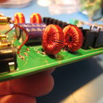
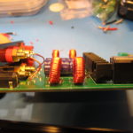
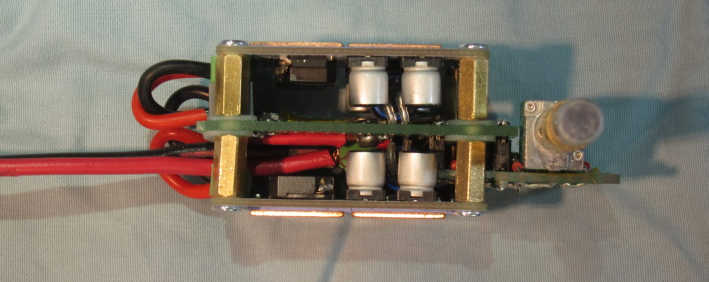
The original version used pin-headers on the mono TPA3110 amplifier modules to connect them to a perfboard motherboard. Connectors for power input and speaker output terminals were on the motherbnoard. The new version uses smaller screw terminals, and moves the speaker output terminals to the amp modules, which are held in place by sandoffs. Pin headers are still used for audio inputs to the modules, and power is still connected to the motherboard, and then supplied to screw terminals on the modules via 18 gauge silicone wire. I also managed a more compact layout for the volume control daughter board.

IMG_8233

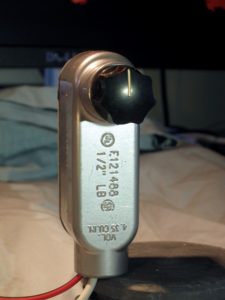
The new version also included improved fit-and-finish to the volume control. I used some aluminum rod and brass tubing to make an extension. This now passes through a drilled-out aluminum plug before being connected to the knob. I’d originally intended to fit a bearing in the plug to support the shaft, but I don’t have one in the proper size (even so, after adjustment shaft alignment is better than pictured).

IMG_0415

I also fitted the thermal pad and copper shims to thermally couple the amp modules to the aluminum case.

Unfortunately, only one channel works. I checked for continuity and power before noticing that a small SMD cap near the PTA3110 chip on the amp board got knocked loose. I’ll have to figure out its specs and try to get and fit a replacement… though it would be easier to just replace the board for $2.50.

I think its a nice improvement. I still need to get wire and connectors I’m happy with the power, speaker, and audio pigtails. Someone suggested 4-pole speakon connectors for the speakers. There is an aluminum version that might be a good match for the case, except it costs about as much as all the other parts combined. There are cheaper plastic speakon connectors that I might try. I’d also like to find a decent pot with an integrated switch I can use to switch the power.

The Conduit: A portable, Class D TPA3110 Audio Amplifier

Update: I made a major revision to The Conduit Amp with some improvements and a bit better fit and finish.

A few months ago I was at the hardware store looking for cheap enclosures for electronics projects. Some aluminum junction boxes for electrical conduit caught my eye, so I bought a couple. In parallel, I was interested in building a small, portable amp that could operate off 12v, which led me to buy some little, mono, TPA3110 modules for a few bucks each.

Surveying my box of parts a couple weeks ago, I noticed that the TPA3110 modules would fit nicely in the smaller of the two junction boxes I purchased, and I started tinkering with ways to assemble them into a finished product.

IMG_0239

The first idea was to join the boards together with standoffs and slip them inside. I ordered some small terminal blocks for the electrical connections. When they came, though, and I tried assembling things as I planned, I realized I’d need to cut the standoffs down in order to fit a board to hold a potentiometer. I was feeling lazy, and didn’t want to deal with metal filings, so I looked for another way.

I decided to use pin-headers to mate the amp modules with small motherboard made from perfboard. For added mechanical strength, I cut the headers with more pins than needed, soldered the pin positions with through-holes on the amp board, and then glued the rest and trimmed them to the same length as the active pins.

Routing the power input and speaker outputs was kind of a nightmare. Rather than trying to plan it all out, I ended up working a couple of connections at once, trying to leave room for the other connections. It took quite a while. I was concerned about some of the routing and figured I’d probably end up doing a second version, so I soldiered on soldering my prototype.

Once I was done, I used my multimeter to check to make sure that there weren’t any short circuits on the motherboard. Fortunately, everything checked out.

Next I had to finish up the input connections and passive volume control. Rather than routing the audio input on the protoboard, I decided to take advantage of the shielding on the input to help keep the signal clean while passing the high-current power and output connections, and the inductors on the amp board. I connected it to the board with the volume-control board at the far end of the case.

After assembling the components on the volume control board I checked everything with a multimeter. Again, I was fortunate that I hadn’t ended up with any shorts. The volume control board was connected to the the “motherboard” with an excess of soldered pin headers for mechanical stability.

I covered the solder pads on the backs of the amp boards with kapton tape to keep them from shorting on the case. Then I made up a power cable and some speaker cables, screwed them in to the terminals on the motherboard and fed them out of the opening of the case.

Maneuvering the amp board into the case with all the cables attached took a bit more force than I was hoping for, a situation not helped by the fact that the position I chose for for the audio input connector interfered with part of the case casting, depriving me of a few extra mm at the opposite side of the case, and putting the volume-pot a bit off center.

IMG_0317

In the end though, I got it to fit.

My plan is to power it off a Quick Charge 2 USB power bank set for 12v output. I have the powerbank, but I still need to make something to negotiate the 12v output, so I powered it off a 12v power brick to test it out.

It works! Even better, it sounds good! So, a second version is a luxury, rather than a necessity. At full volume, the output level with my phone as the audio source is maybe a little lower than I’d like for something intended for use outdoors. I’m not sure yet if that’s a limitation of the 12v supply voltage, or if I need to bump up the gain of the amplifier.

Now that I know it works, I still need to finish it up. I need to fit an extension to the volume potentiometer shaft and pick out a knob that looks good. I also need to put some thermal pads on the bottom of the amp modules to transfer heat to the case. Also I’ll probably find some thinner gauge speaker cable.

Parts Used

Power Rail Noise/Ripple with a Sanwu Blue TPA3118 Mono Class D Amplifier Module

I’m building a few custom audio amplifiers for my personal use out of some inexpensive modules based on the Texas Instruments TPA3118 and TPA3116 Class D amplifier chips.

Class D amplifiers are basically variable switching regulated power supplies (SMPS), which makes them compact and power efficient when compared to traditional amplifiers, which are much more like linear regulated power supplies. The switching frequencies are designed to be well outside of the range of human hearing (and the circuits and transducers we use to reproduce sound) so that it can be filtered without interfering with the audio, and so any remaining signal at switching frequencies is inaudible. In the case of the modules I’m using, the switching frequency is ~400KHz.

The modules I am using have LC (inductor + capacitor) filters on their outputs in order to filter the switching frequency before sending it to the speakers, but I was concerned that the modules would also inject noise onto the power supply rails. TI has provisions for slaving multiple chips together so that they use the same switching clock and can avoid distortion due to interactions on the power supply bus, but the modules I’m using don’t expose the necessary pins, and the small component sizes and spacing between the PCB traces didn’t make me eager to hack them.

Some people have addressed the issue by dedicating a separate power supply to each module, but all things being equal, using a single supply should be cheaper and more compact. I asked for advice on the DIYAudio.com forum, and got some general suggestions, but nothing specific enough to be actionable. I was going to need to do more of the legwork myself.

So, first step, was to see if there were any existing solutions. I started reading datasheets and application notes, but I didn’t find what I thought I needed. I did learn though that, in addition to the switching frequency, Class D amps draw current at either 1x the audio input frequencies, when configured as a half-bridge, or 2x the audio input frequency, when configured as a full bridge.

Next step was to measure magnitude of these potential PSU noise sources in a naive implementation, with no added filtering beyond the PSU’s output filters and the modules PSU input filters.

I used the 24v DC PSU I had handy, an ~10-12 year old 65W Apple 24V PSU intended for a Macintosh PowerBook. I haven’t seen a teardown of the PSU, but in general, Apple seems to put a lot of effort into making their PSUs electrically robust and low noise.

I paired this with a Sanwu “Blue” TPA3118 PBTL mono module. which has ~1320uF (2x 2x 330uF) of electrolytic decoupling caps on the power rails. I then hooked up my oscilloscope and an Analog Discovery to do the measurements.

DS1Z_QuickPrint2

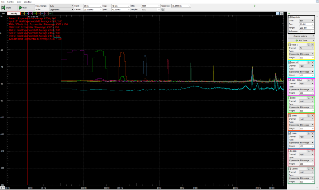
With no signal input to the amp, this is what the power supply rail (yellow) and the amp output (blue) look like. You can see that there is a sinuous ~400KHz, 1.2v peak-to-peak signal on the output from idle switching of the output bridge. You can also see evidence of this switching on the power rail, at the same fundamental frequency, but with a lot of ringing. The 400KHz component is about 50mV peak-to-peak, while the higher-frequency ringing and transients are about 190mV p-p.

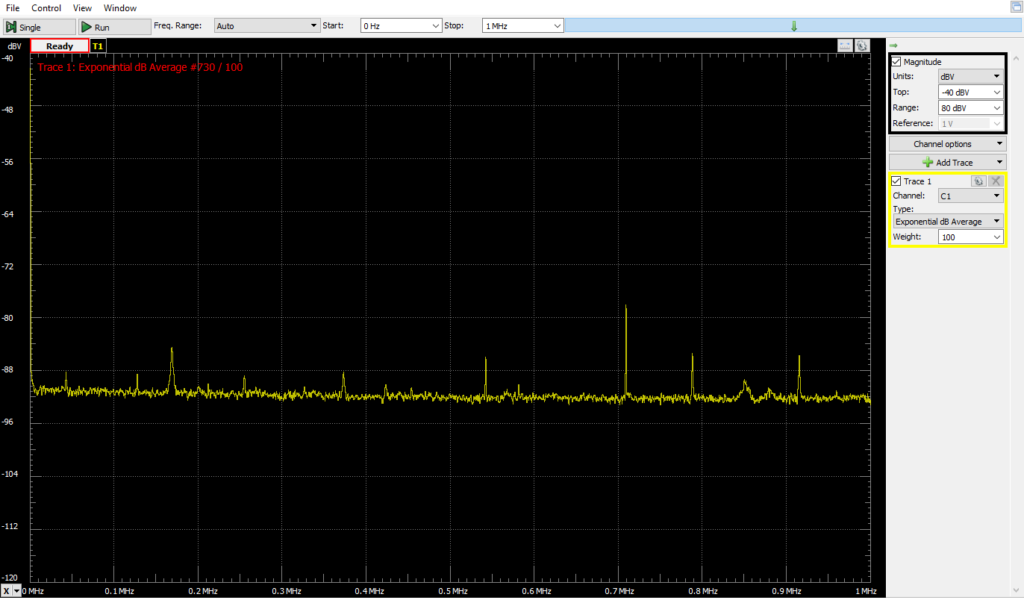
I also took measurements using my Analog Discovery as a spectrum analyzer.

Baseline 1MHz Narrower Y range (similar lashup, no AC power to PSU)

First with everything connected, but no AC power applied to the PSU.

Apple 24v Brick with resistor load

Next, with AC power, and various resistive loads. I was sloppy and didn’t record the exact condutions, but it gives some sense of what the PSU noise is and how it changes with load. Blue is with no load, magenta is with ~30 Ohms, Green is with ~15 Ohms. Also, note, this is a relatively wide spectrum range, from ~0 to 2MHz.

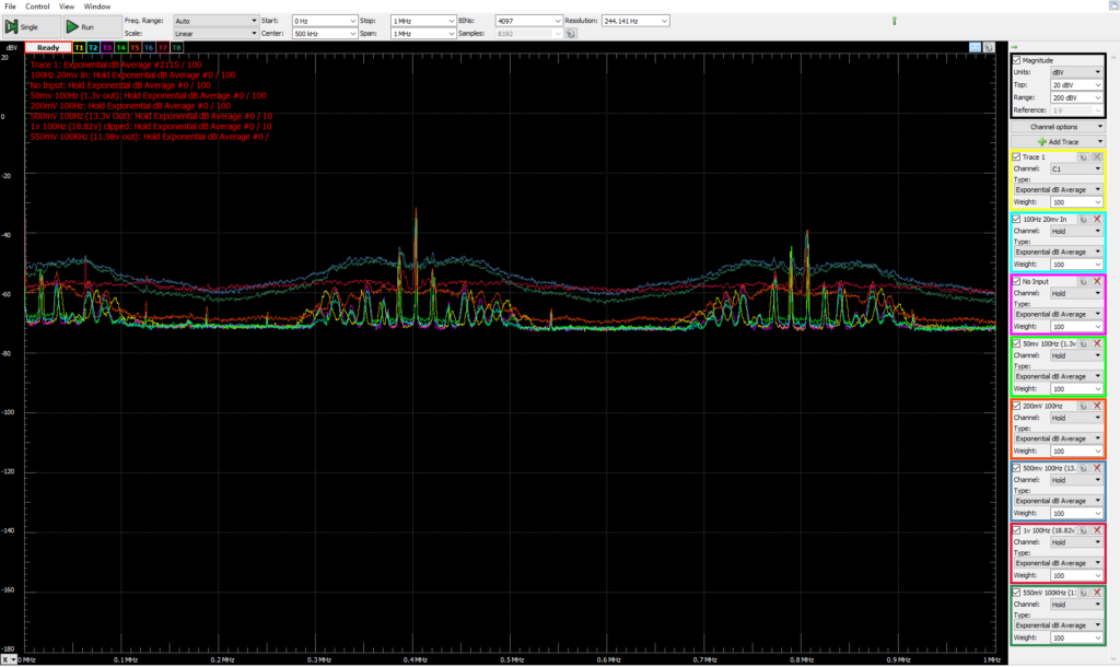
0-1v 100Hz in. multiple traces. 1MHz wide

With the amp as a load (driving a 7.5Ohm power resistor). There is a 100Hz input to the amp. Each trace is a spectrum measurement of the PSU with a different input amplitude, from signal-off to 1v peak-to-peak. These readings were DC coupled, so the measurement reflects the DC voltage component. As a result, the average level for each trace is closer to the baseline as the DC voltage of the PSU rails sags at higher output powers.
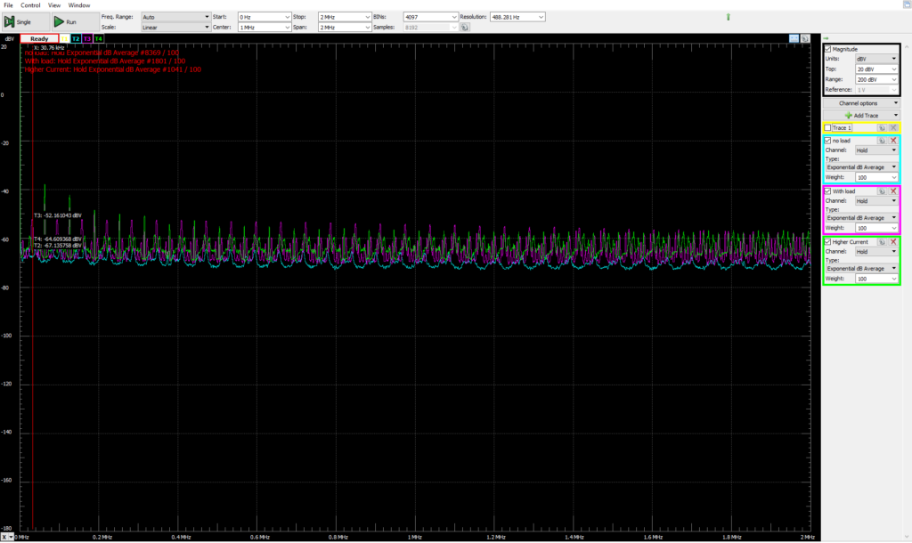
There are peaks at the 400KHz switching frequency, and its harmonic at 800KHz. I’m not sure I understand all the little peaks that group around on each side of the switching frequency.

DS1Z_QuickPrint3

In the time domain, we can see the amplifier-induced PSU ripple & noise in the yellow trace, along with the amplifier output signal from a 500mv p-p, 100Hz input signal. There is a 200Hz ripple on the power supply rail as the amplifier bridge switches on 2x for each input cycle, once to drive the output high, and then again, in reverse polarity, to drive the output low. This ripple is ~500-600mV p-p and its phase is offset a bit from the output waveform. On top of that, you can see the switching noise in the high-frequency “fuzz” on the power supply rail. This “fuzz” is about 1.3v P2P. The two components together add up to ~1.96v of swing.

DS1Z_QuickPrint4

Pushing the input higher quickly runs into problems. With 1v input p-p, things look rather nasty as the peaks get brutally clipped off against the limits of the PSU voltage.

I also took PSU rail frequency measurements with input signals of 50Hz and 10KHz.

40-1280Hz 300mV in

I decided to wrap things up by looking more closely at the impact on PSU voltage at different input audio frequencies. Since the human hearing falls off sharply above 20KHz, and the amp current draw varies at 2x the input frequency, I limited the top of the measurement range to 42KHz. The input signal was 300mv peak-to-peak, and the input frequency was stepped starting at 40Hz and ending at 1,280Hz.

I’m really not sure what the high-frequency peaks are starting at 18KHz or so. I probably should have looked into them more closely.

Now that I have the measurements, I have to make sure I actually understand them before I figure out what to do, and how to do it. I note that in PBTL mode, the chip has a power supply ripple rejection ratio of 75-80dB up to 1KHz, rising to ~55dB at 8KHz and continuing at that level for the rest of the audio range.


SMSL HV-50 Amplifier, anyone?

Does anyone know anything about the SMSL HV-50 amplifier?

s-l1600

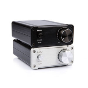
SMSL HV-50

I’m asking, but I think I already know the answer: No, no one knows anything about the SMSL HV-50 audio amplifier, or if they do, they aren’t talking (not in english, anyway). I found a recent reddit thread asking about it, but no one knew much, and I haven’t found much else.
What I do know are some basic details:

  • 50W per channel (stereo)
  • RCA inputs
  • 5-way binding posts for outputs.
  • Based on the TDA7492 Class D Amplifier IC from ST Microelectronics.
  • Aluminum case.

The TDA7492 chip is used in a lot of compact, inexpensive audio amps made by various Chinese manufacturers and sold under various names on Amazon, Ebay, AliExpress, etc.

41ZJRL36sHL

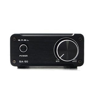
SMSL SA-50

It is also used in the older, almost identically specced 50 Watt/channel SMSL SA-50 amplifier, pictured above. The chip and specs aren’t the only thing the two have in common. As you can see, the case is the same. The only outward difference is slightly different markings and detailing.

The insides are a different story. Both use the same TDA7492 amplifier chip, but as you can see, the PCB and components are quite different.

Last night I noticed that one seller was offering the HV-50 for just $35 with free shipping, so I ordered one. At that price, it was a no-brainer. I’d have easily spent $25 and several hours getting one of the cheap TPA3116 boards I’ve ordered mounted in a suitable case.

I’ll follow up with a new post in a few weeks, once I have the HV-50 in-hand.