The Conduit: A portable, Class D TPA3110 Audio Amplifier

Update: I made a major revision to The Conduit Amp with some improvements and a bit better fit and finish.

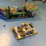
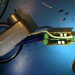
A few months ago I was at the hardware store looking for cheap enclosures for electronics projects. Some aluminum junction boxes for electrical conduit caught my eye, so I bought a couple. In parallel, I was interested in building a small, portable amp that could operate off 12v, which led me to buy some little, mono, TPA3110 modules for a few bucks each.

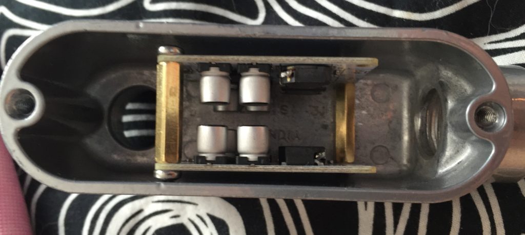
Surveying my box of parts a couple weeks ago, I noticed that the TPA3110 modules would fit nicely in the smaller of the two junction boxes I purchased, and I started tinkering with ways to assemble them into a finished product.

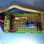
IMG_0239

The first idea was to join the boards together with standoffs and slip them inside. I ordered some small terminal blocks for the electrical connections. When they came, though, and I tried assembling things as I planned, I realized I’d need to cut the standoffs down in order to fit a board to hold a potentiometer. I was feeling lazy, and didn’t want to deal with metal filings, so I looked for another way.

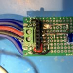
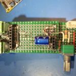
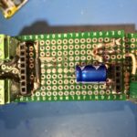
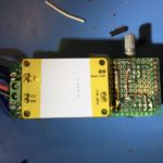
I decided to use pin-headers to mate the amp modules with small motherboard made from perfboard. For added mechanical strength, I cut the headers with more pins than needed, soldered the pin positions with through-holes on the amp board, and then glued the rest and trimmed them to the same length as the active pins.

Routing the power input and speaker outputs was kind of a nightmare. Rather than trying to plan it all out, I ended up working a couple of connections at once, trying to leave room for the other connections. It took quite a while. I was concerned about some of the routing and figured I’d probably end up doing a second version, so I soldiered on soldering my prototype.

Once I was done, I used my multimeter to check to make sure that there weren’t any short circuits on the motherboard. Fortunately, everything checked out.

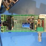
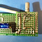
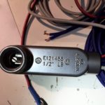
Next I had to finish up the input connections and passive volume control. Rather than routing the audio input on the protoboard, I decided to take advantage of the shielding on the input to help keep the signal clean while passing the high-current power and output connections, and the inductors on the amp board. I connected it to the board with the volume-control board at the far end of the case.

After assembling the components on the volume control board I checked everything with a multimeter. Again, I was fortunate that I hadn’t ended up with any shorts. The volume control board was connected to the the “motherboard” with an excess of soldered pin headers for mechanical stability.

I covered the solder pads on the backs of the amp boards with kapton tape to keep them from shorting on the case. Then I made up a power cable and some speaker cables, screwed them in to the terminals on the motherboard and fed them out of the opening of the case.

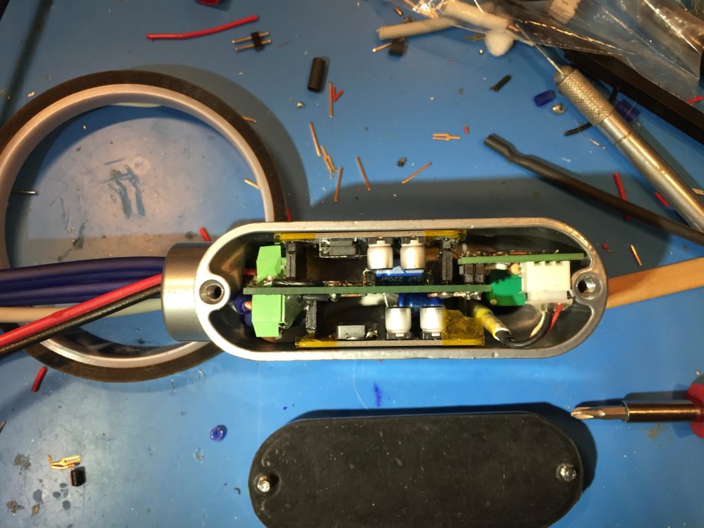
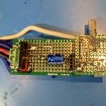
Maneuvering the amp board into the case with all the cables attached took a bit more force than I was hoping for, a situation not helped by the fact that the position I chose for for the audio input connector interfered with part of the case casting, depriving me of a few extra mm at the opposite side of the case, and putting the volume-pot a bit off center.

IMG_0317

In the end though, I got it to fit.

My plan is to power it off a Quick Charge 2 USB power bank set for 12v output. I have the powerbank, but I still need to make something to negotiate the 12v output, so I powered it off a 12v power brick to test it out.

It works! Even better, it sounds good! So, a second version is a luxury, rather than a necessity. At full volume, the output level with my phone as the audio source is maybe a little lower than I’d like for something intended for use outdoors. I’m not sure yet if that’s a limitation of the 12v supply voltage, or if I need to bump up the gain of the amplifier.

Now that I know it works, I still need to finish it up. I need to fit an extension to the volume potentiometer shaft and pick out a knob that looks good. I also need to put some thermal pads on the bottom of the amp modules to transfer heat to the case. Also I’ll probably find some thinner gauge speaker cable.

Parts Used

Power Rail Noise/Ripple with a Sanwu Blue TPA3118 Mono Class D Amplifier Module

I’m building a few custom audio amplifiers for my personal use out of some inexpensive modules based on the Texas Instruments TPA3118 and TPA3116 Class D amplifier chips.

Class D amplifiers are basically variable switching regulated power supplies (SMPS), which makes them compact and power efficient when compared to traditional amplifiers, which are much more like linear regulated power supplies. The switching frequencies are designed to be well outside of the range of human hearing (and the circuits and transducers we use to reproduce sound) so that it can be filtered without interfering with the audio, and so any remaining signal at switching frequencies is inaudible. In the case of the modules I’m using, the switching frequency is ~400KHz.

The modules I am using have LC (inductor + capacitor) filters on their outputs in order to filter the switching frequency before sending it to the speakers, but I was concerned that the modules would also inject noise onto the power supply rails. TI has provisions for slaving multiple chips together so that they use the same switching clock and can avoid distortion due to interactions on the power supply bus, but the modules I’m using don’t expose the necessary pins, and the small component sizes and spacing between the PCB traces didn’t make me eager to hack them.

Some people have addressed the issue by dedicating a separate power supply to each module, but all things being equal, using a single supply should be cheaper and more compact. I asked for advice on the DIYAudio.com forum, and got some general suggestions, but nothing specific enough to be actionable. I was going to need to do more of the legwork myself.

So, first step, was to see if there were any existing solutions. I started reading datasheets and application notes, but I didn’t find what I thought I needed. I did learn though that, in addition to the switching frequency, Class D amps draw current at either 1x the audio input frequencies, when configured as a half-bridge, or 2x the audio input frequency, when configured as a full bridge.

Next step was to measure magnitude of these potential PSU noise sources in a naive implementation, with no added filtering beyond the PSU’s output filters and the modules PSU input filters.

I used the 24v DC PSU I had handy, an ~10-12 year old 65W Apple 24V PSU intended for a Macintosh PowerBook. I haven’t seen a teardown of the PSU, but in general, Apple seems to put a lot of effort into making their PSUs electrically robust and low noise.

I paired this with a Sanwu “Blue” TPA3118 PBTL mono module. which has ~1320uF (2x 2x 330uF) of electrolytic decoupling caps on the power rails. I then hooked up my oscilloscope and an Analog Discovery to do the measurements.

DS1Z_QuickPrint2

With no signal input to the amp, this is what the power supply rail (yellow) and the amp output (blue) look like. You can see that there is a sinuous ~400KHz, 1.2v peak-to-peak signal on the output from idle switching of the output bridge. You can also see evidence of this switching on the power rail, at the same fundamental frequency, but with a lot of ringing. The 400KHz component is about 50mV peak-to-peak, while the higher-frequency ringing and transients are about 190mV p-p.

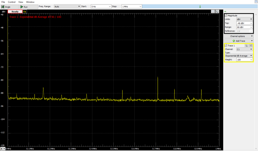
I also took measurements using my Analog Discovery as a spectrum analyzer.

Baseline 1MHz Narrower Y range (similar lashup, no AC power to PSU)

First with everything connected, but no AC power applied to the PSU.

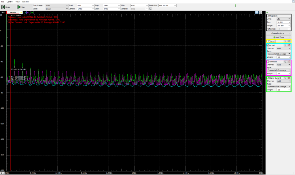
Apple 24v Brick with resistor load

Next, with AC power, and various resistive loads. I was sloppy and didn’t record the exact condutions, but it gives some sense of what the PSU noise is and how it changes with load. Blue is with no load, magenta is with ~30 Ohms, Green is with ~15 Ohms. Also, note, this is a relatively wide spectrum range, from ~0 to 2MHz.

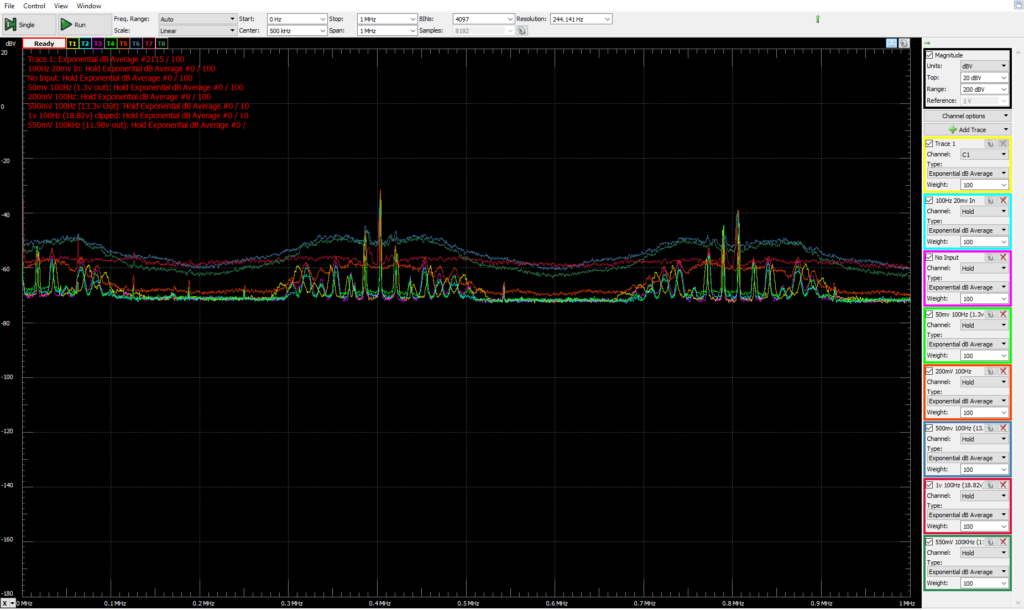
0-1v 100Hz in. multiple traces. 1MHz wide

With the amp as a load (driving a 7.5Ohm power resistor). There is a 100Hz input to the amp. Each trace is a spectrum measurement of the PSU with a different input amplitude, from signal-off to 1v peak-to-peak. These readings were DC coupled, so the measurement reflects the DC voltage component. As a result, the average level for each trace is closer to the baseline as the DC voltage of the PSU rails sags at higher output powers.

There are peaks at the 400KHz switching frequency, and its harmonic at 800KHz. I’m not sure I understand all the little peaks that group around on each side of the switching frequency.

DS1Z_QuickPrint3

In the time domain, we can see the amplifier-induced PSU ripple & noise in the yellow trace, along with the amplifier output signal from a 500mv p-p, 100Hz input signal. There is a 200Hz ripple on the power supply rail as the amplifier bridge switches on 2x for each input cycle, once to drive the output high, and then again, in reverse polarity, to drive the output low. This ripple is ~500-600mV p-p and its phase is offset a bit from the output waveform. On top of that, you can see the switching noise in the high-frequency “fuzz” on the power supply rail. This “fuzz” is about 1.3v P2P. The two components together add up to ~1.96v of swing.

DS1Z_QuickPrint4

Pushing the input higher quickly runs into problems. With 1v input p-p, things look rather nasty as the peaks get brutally clipped off against the limits of the PSU voltage.

I also took PSU rail frequency measurements with input signals of 50Hz and 10KHz.

40-1280Hz 300mV in

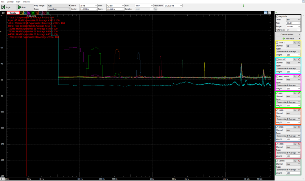
I decided to wrap things up by looking more closely at the impact on PSU voltage at different input audio frequencies. Since the human hearing falls off sharply above 20KHz, and the amp current draw varies at 2x the input frequency, I limited the top of the measurement range to 42KHz. The input signal was 300mv peak-to-peak, and the input frequency was stepped starting at 40Hz and ending at 1,280Hz.

I’m really not sure what the high-frequency peaks are starting at 18KHz or so. I probably should have looked into them more closely.

Now that I have the measurements, I have to make sure I actually understand them before I figure out what to do, and how to do it. I note that in PBTL mode, the chip has a power supply ripple rejection ratio of 75-80dB up to 1KHz, rising to ~55dB at 8KHz and continuing at that level for the rest of the audio range.