Still Shopping for my first oscilloscope, but it’s selection time!

I recently decided to buy my first oscilloscope to help with the process of learning more about electronics. The process of selecting an oscilloscope has been longer than expected. I started by looking at the scopes that Sparkfun and Adafruit offered, which lead me to wonder what other options were out there. I was a bit overwhelmed at the variety of models and manufactures, but managed to cut through a lot of the noise.

In this post, I’ll talk more about how I narrowed things down further, and what I ended up choosing.

To start, its worth covering why I wanted an oscilloscope in the first place. It all stems from a growing interest in the declining costs of capable “systems on a chip,” low power communication technologies like Bluetooth LE, and even WiFi, and the accessibility of the Chinese electronics manufacturing supply chain. Taken together, it seemed to me that I should learn enough about electronics to have a sense of the possibilities and limitations, and to be better able to collaborate with people with deeper expertise. This approach served me well in the past when I worked on software projects; I wasn’t a programmer, but I understood enough to be a good collaborator.

In looking around for learning projects, I decided to explore the world of power sources for these devices with a new site called Power Cartel. Part of what I’m doing on Power Cartel is doing teardowns of battery packs and chargers, with the goal of collaboratively creating useful opensource designs. In order to dive deeper in my teardowns, and support my own design efforts, I need to be able to start exploring what is happening inside the circuits and understanding how the different components interact.

There are a lot of test instruments. I already have a basic multimeter, but I felt like I needed a way to look at signals over time. There are two instruments that fit that job description. A data logger or chart recorder is useful for looking at signals over long periods of time (ie hours), where as an oscilloscope is good for looking at signals over much shorter periods, seconds down to micro, or even nanoseconds. I actually want to look at signals over both time periods. I want to look at current and voltage for charging and discharging batteries over the period of hours or days, but I also want to look at sub-second changes in signals.

I decided to start with an oscilloscope, rather than a data logger, because the sub-second changes are more fundamental. With a better understanding of such things, I could build my own data loggers. Moreover, most modern digital storage oscilloscopes can actually record signal changes over longer periods of time, and they can be connected to a computer for control and data recording.

I originally thought that some sort of oscilloscope module that I could connect to my computer or iPad would be a good place to start because it would save me money and space. I quickly learned there were problems with that approach. Most electrical engineers and technicians are trained on traditional stand-alone oscilloscopes, and training aside, traditional stand-alone oscillosopes are often easier/faster to work with because they have dials and buttons arranged in a user interface that has seen steady improvement for close to a century. Connected scopes are newer, and more of a niche item, so their software is less refined. More importantly, because they are a niche item, there is less competition and scale to push prices down, so any savings that might come from omitting a screen and controls is offset. As a result, USB scopes are not any cheaper than stand-alone scopes with otherwise similar specifications. The space savings was still attractive, but I decided I was going to purchase a stand-alone scope.

With that decision made, I had to figure the other key specifications for my work. For any scope, whether an older analog scope, or a more modern digital storage scope, bandwidth is a key consideration. Bandwidth determines the range of signal frequencies you can measure with the scope. Adafruit sells scopes with 50MHz and 100MHz bandwidth. Sparkfun’s stand-alone scope offering is 100MHz. From a little reading, the switch mode power supplies I’m going to be working with typically operate in the range of 200KHz to 2MHz, and the microcontrollers I’m working with operate at 4-16MHz, or perhaps 50-70MHz. Some of the wired communications protocols I’m using may be 5MHz.  It would seem then that a 50-100MHz scope would cover almost anything I’m likely to use it for in the near future.

Closely related to bandwidth is the sampling rate. Sampling rate is the number of times per second a signal is read. For a pure sine wave, an accurate estimate of frequency and amplitude requires a sampling rate that is at least two times higher than that of the signal being measured. One of the big reasons for having an oscilloscope though is to look at signals that are not pure sine waves. A lot of digital communications use square   wave signals, and a lot of signals, whether square, sign, step, pulse, or something else, can get distorted by characteristics of the circuits they travel in. A rule of thumb I’ve come across is that the sample rate should be 4x the frequency of the signal you are observing.

Almost all the scopes in my price-range ($400-650) have a 1GHz max sample rate. That may sound like overkill for a 100MHz scope, but in this segment of the market, that sample rate is across all the channels of the scope. So, if you have a scope with two channels, and you are using both of them, thats a 500MHz rate per channel, which is closer to the rule of thumb.

The next thing I considered was the number of channels. Each signal you measure requires a channel. Often you are comparing two signals against each other some how, and so, not surprisingly, most scopes have at least two channels, and, indeed, in this entry level segment, most don’t have more than two channels. I found a few with four channels, though. Most were out of my price range, but one, the Rigol DS1074Z was available for under $600. A two channel scope would probably do everything I reasonably needed, but the option of having four channels was intriguing. Four channels would allow me to look at voltage and current at the same time for both the input and output of a power supply. Even better, I could use some of the channels as a basic logic analyzer, and look at how analog signals changed in relationship to specific digital signals.

The consideration of the number of channels also turned my attention to scopes with a logic analyzer option to look at even more digital signals. Oscilloscopes with this feature are generally called Mixed Signal Oscilloscopes, which add 8 or 16 logic channels. The added digital channels come with an added cost. There is a $600 mixed-signal scope from Rigol (DS1052D), but it only has two analog channels, 50MHz bandwidth, and 1Mpts of memory. The Rigol MSO10747Z, which is the mixed signal version of the DS1074Z is $250 more expensive, and out of my price range. Since people seemed less bothered by USB logic analyzers, and since a cheap one could be had or $20 or so, I decided that I didn’t need a full logic analyzer.

Another consideration is the amount of memory available to hold samples. The Rigol DS1074Z has memory for twelve million sample points (12Mpts). Some of the alternatives I considered, like the Siglent SDS1102CML only has 2Mpts of memory, and the Siglent SDS1074CFL only has 24Kpts.

By now, you’ve probably figured out the DS1074Z is the scope I’m leaning towards. I took repeated looks at the other options from Rigol and Siglent, but kept coming back to the DS1074Z.

Comparison

Cheaper

  • Siglent SDS1072CML for $319: +lower price -2 channels -memory
  • Rigol DS1052E for $329 +lower price -50MHz -2ch -smaller screen – older
  • Siglent SDS1102CML & SDS1102CNL ~$360 +lower price +100MHz -2ch -smaller memory -can’t tell how they differ from each other, other than memory
  • Gatten GA1102CAL $400 +lower price +100MHz -2ch -smaller memory

I would have liked spending less, but I wasn’t willing to go with a last generation Rigol, or forgo 2 channels and a bunch of sample memory just to save $150 or so

Similar

  • Siglent SDS1202CNL+ $546 +200MHz, 2Gigasamples/s -2ch -memory
  • Rigol DS1052D $610 +16 channel logic analyzer, -2ch -memory

The higher bandwidth and sample rate of the Siglent just didn’t seem that compelling, and nor did spending another $60 for the 16-channel logic analyzer on a last generation instrument.

More Expensive

  • Siglent SDS1074CFL $723 -higher price +2GSa/s, =4ch, – memory
  • Siglent SDS2072 $805 -higher price, +2GSa/s +memory -2ch +larger screen
  • Rigol DS1074Z-S $818 +signal generator
  • Rigol DS1104Z $830 +100MHz bandwidth
  • Rigol MSO1074Z $835 +16 channel logic analyzer
  • Rigol DS2072A $839 -higher price -2ch +2GSa/s

The price was really enough to knock all of these out. The Siglent SDS1074CFL was tempting since it had 4 channels and a higher sample rate, but the higher sample rate isn’t that important to me at this point, and so not worth the extra $175 or so. The only other one I gave serious consideration to was the MSO1074Z, but the integrated logic analyzer just didn’t seem compelling enough to drop another $280 or so.

Finally

In the end, the Rigol DS1074Z won me over with its combination of price, four channels and deep memory, along with the fact that Rigol seems to be a well-understood quantity at this point. This model has been out for almost a year, most of the bugs are known, and many have already been address. There are lots of good in depth reviews and tutorials for Rigol scopes. Certainly more than I saw for Siglent/Atten/Gatten or Owon.

The Rigol has another thing in its favor. It apparently shares the same hardware as the DS1104Z, and people have figured out a way to unlock the higher bandwidth. They’ve also figured out how to unlock some otherwise extra cost after market options, most of which don’t interest me, but its nice to have the option.

I ended up ordering my scope from TEquipment.net, and paid less than $585 with free shipping thanks to a discount they offer members of EEVblog.


Apple Event Live Blog September 19 2014

In which I sit in my office in Seattle, watch the Apple live stream and comment on it:

  • 10:04am PDT
  • I still see the test pattern and schedule. This never would have happened when Steve Jobs was Alive.
  • 10:06am
  • Time Cook is on, and then the bars come back…
  • 10:08am
  • Ok, its working again…and fail.
  • 10:11am
  • It is working again, for now…
  • Bigger phones, um, hooray? I guess.
  • Phil is talking about % more pixels. Lame…
  • Now he’s finally talking about why that matters: two up view.
  • Thinner is good though, I guess, as long as it feels solid.
  • What is with the translation track?
  • And the stream breaks again…
  • Something about apps taking advantage of larger displays.
  • Desktop-class scaler?
  • 10:24, it is working again…
  • A8+METAL = FAST GRAPHICS
  • BETTER BATTERY LIFE
  • New M8 co-processor.
  • Distance and elevation estimation.
  • Ok, so, I do want one, just to be clear. My iPhone 4s seems a little too old now.
  • 10:28am
  • Cameras
  • Hmm. Focus pixels?…   Phase detection autofocus!!! Fast autofocus!  YES I MUST HAVE THIS!
  • Something about the macro mode that I didn’t catch.
  • 10:34am
  • Apple broke the internet.
  • 120 or 240fps video. Sweet
  • Continuous focus for video…
  • 10:36am
  • More stream breakage
  • 64GB for the mid-range for $299 on contract!  Yay
  • $100 for thoe the 6plus
  • Steady incremental improvement can really add up. I was pretty “meh” leading up to this event. I felt the same way when it started, but everything adds up.
  • The payment stuff seems pretty important, especially the API…
  • One more thing…
  • It would be really really awsome if it isn’t a watch.
  • Its a new planet!
  • And the space ship that will get you there
  • No, it really is a watch…
  • I must say, it looks really cool…
  • …for a watch.
  • I’m so over watches…
  • At least I thought I was…
  • For 10-15 years…
  • At least it isn’t called iWatch.
  • The personal touch stuff is really interesting…
  • I wonder if 3rd party developers will be able to create “watch face” apps.
  • I look forward to the bio-mimetic bands for the next version.
  • They will graft themselves into your skin.
  • Or rather, your skin will incorporate them.
  • This is a long-ass video.
  • Why does Kevin Lynch seem familiar…
  • He’s the former Adobe Flash Evangelist
  • Gruber called him a bad hire for Apple…
  • Coldplay?  What a fucking bozo.
  • 3rd party dev support sounds pretty good.
  • I’m running out of steam here…
  • I wonder how the Apple watch works when you don’t have your phone with you?
  • The live stream was working so well, until, another fail.
  • So, if Apple Pay is built into Apple watch, and Apple watch works with many versions of iPhone, plus all the accessories, Apple has multiple revenue streams for the Apple watch. I wonder if the pricing will be subsidized.

Still shopping for my first oscilloscope

Earlier I wrote a long blog post that condensed down the path I’ve taken to buying my first oscilloscope. I hadn’t decided what to buy though., so this post will continue with more of the decision making process.

But first, a short review of the ground I covered in my earlier post. I explained that I needed an oscilloscope to help me better understand why circuits work, or don’t work. I’m not just doing this for fun, my goal is to start designing and building some useful circuits of my own. I covered how I started figuring out what my options were for an entry-level scope, in order to better understand what I should be thinking about.

At the end, I’d concluded that buying a cheap compact oscilloscope like the DSO Quad wasn’t a good idea (not capable enough to be useful for long, and not cheap enough given its limitations), and why a USB scope wasn’t going to save me any money (the meager savings from omitting a screen and controls are offset by the higher prices that come with limited volumes).

I started by considering Rigol scopes like the dual-channel Rigol scopes sold by Adafruit, or the dual-channel. Gratten scope sold by Sparkfun. At this point though, I’ve all but ruled out those options. The truth is, at $390-460, they are all within my budget, and with 50-100MHz of bandwidth, they can all do what I think I’m going to need them to, which is to deal with ~1-2MHz signals from switch mode power supplies. The problem is, while I don’t know much about oscilloscopes, I’ve already figured out that I have better options.

A hint of this is already obvious among the three scopes on Adafruit and Sparkfun. Both the Rigol scopes have 5.7″ 320x24o displays, while the Gratten has a 7″ 800×480 display. Of course, even I know that while a large screen is better, screen size probably shouldn’t be the first, or even fifth thing to judge a scope on. Things like bandwidth, sample rate and memory size, on the other hand, are much more important, and here the Gratten scope matches or beats the Rigol offerings sold by Adafruit. For $400, it offers 100MHz bandwidth and it does so for just $10 more than the 50MHz Rigol scope and $50 less than the 100MHz Rigol. That might be enough to convince them to buy the Atten scope from Sparkfun, me, on the otherhand, I get curious about what else is out there.

What I found is daunting. There are so many options, I’m tempted to buy the Gratten GR1102CAL from Sparkfun and get on with things, but that wouldn’t be like me. I press on.

One of the things I notice in my research is that a lot of these scopes have similar model names. This isn’t exactly a surprise though, because often the numerical part of the name represents some fundamental characteristics. Taking the Sparkfun and Adafruit offerings as an example:

  • DS1102
  • DS1052
  • GR1102CAL

The last/right-most digit on all three scopes is the number two (2). If one were to check out more models of scope from Rigol and Atten (among others), you’d probably recognize that this is the number of input channels. Two channels is common among entry level scopes. Higher end scopes sometimes have 4 channels.

With enough perspective, it becomes obvious that the middle two digits often indicate the bandwidth offered by the scopes: 100MHz or 050MHz in the case of these examples.

The meaning of the first digit seems to indicate the model line, and the letters at the end often indicate key options, like memory size.

The similarities don’t end with just the numbers though. Model names between manufacturers seem very similar. Sometimes even the names seem similar. For example, there is the Gratten GR1102CAL sold by Sparkfun, and there is another manufacturer called Atten, which has a model SDS1102CAL; the specs are pretty much identical between the two. In fact, the case is too, down to the position of the front USB port. Oh, and then there is the Siglent SDS1102CAL, also with remarkably similar specs and appearance.

There is an explanation though, which is that some manufactures sell the same or similar equipment under multiple brands and/or sell equipment which other brands sell under their own label. This simplifies things somewhat, if you can keep everything straight.

I learned something else too, which is that while the Rigol scopes Adafruit sells were revolutionary revolutionary for the value they offered when they first came out, they are a bit long in the tooth now. Last year Rigol released the DS1000Z series, which occupies the same price point the DS1000 series originally did when it came out.

I’ve learned a lot more about the options available for good entry level scopes. Now I’m really sure that I don’t know what to buy. Narrowing down my options will have to be the subject for a new post


Shopping for my first Oscilloscope

My new project is going to involve testing and designing electronics, and so I find myself in need of a bunch of tools I don’t have. Foremost among them, is an oscilloscope, so I can probe circuits in devices to try and understand how they work, and why they don’t work.

My overall electronics aptitude is pretty mediocre. I had a job soldering connectors to serial cables when I was a kid, but my soldering skill isn’t very high and most of the electronic theory I learned in my introductory physics course in college is long forgotten. I have used an oscilloscope though. I used one when I learned about electrophysiology techniques for looking at the activity of individual cells, and I also used one to tune the video system of a cell-florescence microscope to take full advantage of its dynamic range.

More important than what I’ve done with oscilloscopes is that I know what I’d use one for now. I think it will come in handy for looking at the operation of DC-DC power supplies, and just generally for probing circuits. Beyond that though, I’m a novice, and so I went looking a place to get advice. Actually, I didn’t have to look, because I’d already found the EEVBlog Forum, which even has a special section where people are supposed to go easy on beginners for asking dumb questions. Still, they ask that you provide plenty of information when you ask a question, so I had to do some shopping on my own, so I could get a sense of the questions I should ask, and the background I should give.

My first stop was to see what Sparkfun and Adafruit, two online stores that specialize in electronics for hobbyists, were offering. Adafruit has two options, one a 50MHz, two-channel Rigol DS1052E digital storage oscilloscope, the other, a Rigol DS1102, is very similar, but has 100MHz bandwidth. Sparkfun offers the Gratten GA1102CAL, which is also a 100MHz, 2-channel digital scope. They also have two USB scopes for use with your computer, the MSO-19, and MSO-28 from link instruments. Sparkfun and Adafruit also both carry the small, inexpensive DSO Nano and/or DSO Quad.

I’d been considering a DSO Nano or Quad because of their low price and compact size, but people who seem to know better hate them, first because their user interfaces are difficult to use compared to a real oscilloscope, but also because they can’t actually do much. Of course, my needs, as I understand them, aren’t that demanding. I think the signals I’ll be looking at are in the 1-2MHz range, which should be within the capabilities of the DSO Quad, but it doesn’t leave a lot of headroom, and at $200 bucks, its a bit too expensive given that you could get a more capable used analog scope for less, or a new digital scope for another $50-100 more.

I also considered a USB scope. They are more compact, and I also assumed they’d be cheaper, since they didn’t have to include a screen or UI, and I also thought it might make it easier to work with the data on a computer. I was wrong on multiple counts. USB Scopes are a bit of a niche item when compared to a benchtop scope, because regular O’scope users find physical knobs and buttons more productive and easier to use than the often poor software that ships with USB scopes. As a result, volumes are lower, and there is less competition to drive prices down. Moreover, screens are pretty cheap these days, so eliminating one isn’t a huge cost savings. Put the two together, and a decent USB scope is about as expensive as a dedicated scope with similar specs, and you can hook most dedicated scopes up over USB if you need to anyway.

Exploring the existing options helped me think through what I needed and why. I was ready to ask the experts over on EEVBlog. I’ll cover that in my next blog post.

DIY Downsides: When successful troubleshooting deprives you of an excuse for upgrading.

The same base urges that led me to upgrade my home server, have had me itching to upgrade my home network. The server build sated that hunger for a while, but now that it is done, I’ve been feeling the pull, again. I’ve held out, but yesterday, I thought I was going to HAVE to upgrade because one of my routers started acting up. Happily/sadly, successful troubleshooting has stimied such rationalizations.

The current network arrangement consists of a Netgear WNDR3800 running OpenWRT as the main router/firewall. It has direct connections a couple of small ARM servers running Debian, which run various services. It also provides WiFi access. At the other side of the house, there is another router, a Netgear WNDR3700, also running OpenWRT that is bridged to the main router over 5GHz WiFi. It provides wired connectivity for a printer, a server, and a Acu-Link bridge that connects a weather station to the Internet. It also provides WiFi access in the 2.4GHz band and guarantees decent connectivity from our back yard.

I’ve been considering various options for upgrading, with the goals of getting a higher-speed link between the two routers, and a speed bump for my laptop, which has a 3-stream radio, whereas the routers are limited to two streams. I wasn’t entirely happy with any of the options though, which is one of the reasons I’d been able to resist the upgrade urge.

Yesterday though, as I’ve already mentioned, things started getting flakey. I noticed that the second router seemed to be rebooting every ten to fifteen minutes, interrupting connectivity for connected devices for a good 60-90 seconds. I could have used this as an excuse to upgrade, but I tried to troubleshoot the problem first.

I’d recently moved some equipment around, so the first thing I checked was that the power cord hadn’t been partially unplugged. It didn’t seem like it had, but I made sure it was well plugged in and waited to see if the problem continued. It did.

As part of the equipment moves, I’d swapped in a higher-capacity UPS. The UPS had been functioning just fine, in its previous location, but I wondered if it was adding noise that the routers power supply was having trouble contending with, so I swapped in another 12V DC wall wart. At first, that seemed to solve the problem, no reboots in over 20 minutes, but before another 20 minutes were over, the router rebooted again.

I wondered if it was a temperature issue. It was a warm day, though no warmer than other days this summer. I decided to take the router apart to see if there was any dust slowing down convection from the case. Once I got the case open though, I realized that I’d already opened and cleaned out the router a few weeks before. Back to the drawing board.

I decided to open up an SSH session so I could watch the system log (OpenWRT logs to a ring buffer in memory, so you have to use “logread -f.” in the hopes that I’d see something useful before the device rebooted itself. Once I had that running, I took my dog for a ~60 minute walk. When I returned, the router was still running, still logging to my screen. I scrolled back over the logs, and didn’t see anything unusual. I started to wonder if it was a “heisenbug.” Perhaps I was going to have to upgrade after all.

The log filled with information about connections and disconnections from WiFi devices, and IPv6 related housekeeping. A few minutes later though, something different flashed past on the console. I scrolled back and saw that the kernel reported that it detected a low memory condition and killed off a maintenance script to keep from running out of memory. I thought it strange, but I didn’t see what would have changed to make low-memory conditions commonplace, or how they’d lead to a reboot. It was, however, my only lead, and as I sat there thinking it over, I saw another low memory warning.

It was starting to make sense, I imagined how the router could get in a situation where it killed off an essential process and ended up rebooting. It might even be that the router hardware had a watchdog function, which would reboot the device if a process didn’t reset the watchdog timer on a regular interval. Killing that process could lead to a reboot.

Now that my only lead was starting to seem plausible, I dug deeper. I first checked the amount of memory in use with the “free” command. It reported there were less than 2MB free, which surprised me since I remembered it was typically many times that. Next I used “ps” to see what processes were running, and which were using the most memory. None of them were obviously huge, but a few of the larger processes didn’t look quite right.

I have an Acu-Rite weatherstation and an Acu-Link bridge. The bridge relays readings from the weatherstation to Acu-Rite’s servers. I have a system in place to capture the data as it is being transmitted, and feed it to Weewx on one of my servers. Weewx keeps its own record, and also updates Weather Underground. To accomplish this, I have a startup script on the secondary router that uses “ncat” to wait from an incoming connection from the driver I wrote for WeeWX. Once the connection comes in, ngrep sniffs for packets from the Acu-Link bridge relaying data from my weather station to the internet service. That data forwarded overmy network to the waiting weewx driver on my server.

The problem was that there were 3-4 copies of these processes running on the router. Ordinarily, there should only be one. After a connection is lost temporarily and weewx has reconnected, there might be two running before the old copy times out. I tried reducing the max number of connections from four to two, which helped a bit, but it was still cycling the connection much to quickly and for no obvious reason.

I tried restarting weewx, but that didn’t help, it was still connecting and then disconnecting too frequently. To debug things further, I decided to simulate the server connection and see if the data was being captured and forwarded properly. It wasn’t!

From here, I wanted to connect to the diagnostic webserver running on the Acu-Link to confirm that it had a connection to the weather station. I looked at the main router to find the Acu-Link’s IP address, and in the process I realized that it had changed. I hadn’t created a DHCP reservation for the Acu-Link device because DNSMasq, which provides DHCP service on the router, generally provides a stable IP address to devices. Something had happened though, probably when I was moving around hardware, and it had assigned a new IP address.

So, to recap:

  1. My script was depending on a result of the default behavior of DNSMasq for the IP address of the Acu-Link bridge.
  2. As a result of reconfiguring my network, something changed, and with it the result of that default behavior, leading to the IP address of the Acu-Link bridge changing.
  3. As a result, of the changed IP address, my script for sniffing weather data failed to collect that data and forward it to weewx running on my server.
  4. Because it wasn’t getting data as expected, weewx tried to reconnect to the sniffer script.
  5. Because weewx was reconnecting as frequently as it was, excess copies of ncat, ngrep and the ash shell accumulated on the router, eating up memory.
  6. Because of the low memory condition, the kernels out of memory killer (OOM killer) started killing off processes.
  7. Because some key process was killed by the OOM killer, the router rebooted, continuing the cycle.
  8. Because the router was rebooting frequently, I decided to troubleshoot it.
  9. Because I succeeded in troubleshooting the root cause, I have removed a reason to buy a new router.

Sometimes being awesome has to be its own reward, I guess.

Since I couldn’t in good conscience buy a new router, I did a few easy things to fix the problem. I configured the DHCP server to assign a predefined IP to the Acu-Link bridge, and update the script to look for packets from that IP.

There additional mediations to this issue that I probably won’t undertake, including:

  1. Updating my WeeWX driver to make sure it properly cleans up sockets when reconnecting. This might lead to quicker cleanup of the old processes on the router.
  2. Updating my WeeWX driver to throttle the rate at which it retries connections.
  3. Trying to automatically detect the IP of the Acu-Link bridge and then use that IP for the ongoing packet sniffing.
  4. Adding some code to the sniffer script that will be more aggressive about cleaning up unused connections.


ASRock AM1B-ITX + AMD Kabini Sempron 3850 Linux Notes

Earlier this summer I built a new home server using an ASRock AM1B-ITX motherboard and a AMD Kabini Sempron 3850 CPU.

To make a long story short, this motherboard doesn’t work well for my intended use as a headless Linux server. The problems are manifold and interconnected:

  • If I boot headless, it decides the integrated GPU isn’t being used.
  • Once it decides the integrated GPU isn’t being used, it tries to use a PCI Express GPU, which it doesn’t find.
  • At some point, it also reactivates compatibility mode.
  • With compatibility mode activated it is, ironically, incompatible with my combination of hardware.
  • The combination of all of the above means that it won’t boot headless.


These issues weren’t immediately obvious. The storage issues showed up early on, once I added the extra drives, but others took longer to show their face because, while I’ve been using it for its intended purpose for a couple of weeks now, I only just finally got around to moving it off the corner of my desk and into its final position on a shelf in a closet. I assumed this move would be relatively uneventful. It wasn’t, it was frustrating and tedious.

By way of context, I thought I’d give a few more details on my installation.

The system drive is a 256gb Crucial MX100 SSD. The root volume is relatively small, like 8GB or so. There is a small swap partition, an EFI partition, a good chunk of unused space  as a lazy sort of SSD over-provisioning for longer life, but the bulk of the drive is set aside as for SSD caching of various volumes using Bcache. The root volume is un-exotic though, straight ext4. I’d intially set the system up to boot using legacy BIOS, but after some backflips, managed to convert it to use gpt partitions, and UEFI booting.

The SSD is connected to the main SATA3 controller on the Kabini SoC, as is a 3TB Western Digital Red drive. There are two other motherboard SATA3 ports provided by an ASMedia chip. These are attatched to  3TB and 1TB WD Green drives. None of this is very exotic.

The CPU/Motherboard has integrated video, which I had attached over DVI to an external monitor. The machine is intended to run headless, but I want to run some OpenCL stuff on the GPU, so I had to install video card drivers. By default, the system installed the open source radeon driver, but, from what I could tell, this doesn’t yet have OpenCL support, so I switched to the proprietary binary flgrx driver.

With that background out of the way, I’ll detail the many annoyances I’ve had with this system.

First off, I found that it would often boot slowly, or hang all together, and this tended to involve drives connected to the ASMedia SATA controller. Sometimes it would hang or take forever to detect connected drives. Other times, it would hang on the main BIOS screen, while lighting an activity light on one of those drives. After some trial and error, I figured out it worked much better if I disabled “Compatibility Support Mode” (CSM) in the boot section of the BIOS setup.

The next problem came when I shut the machine down, detached it, and moved the machine to its final location. When I rebooted it, it emitted 5 sharp beeps and then didn’t seem to do much of anything else, except light up the activity light on one of the drives connected to the ASMedia controller. I tried leaving it for a while, to see if it proceeded to boot, but finally gave up and tried resetting it. That didn’t work either, no beeps this time, but it still seemed to hang with the drive light activated. I moved it back to the desk, hooked up the monitor and tried to figure out what had gone wrong.

I found that the BIOS seemed to have reverted back to compatibility mode, moreover, the primary GPU was listed as being PCI Express, rather than integrated. A little digging and I learned that the 5 beeps meant “without vga card.” I mucked around a bit more, trying different things, before reaching the conclusion that this board has major problems, at least for my application.

I’m not sure what I’m going to do next. I realize it might be worth disabling the boot recovery mode, because that may be part of the reason it is falling back to a problematic BIOS configuration. My guess is that I may still have trouble with the internal video, but I might be able to address that with an explicit kernel option (assuming that the boot process still continues). Another option is to see if I can hook something to one of video ports that tricks it into thinking a monitor is connected.

KMASHI 10,000 mAh USB Power Bank / Backup Charger Teardown

I decided to buy a USB “power bank” or backup external battery to keep in my backpack to recharge my phone or iPad when I am away from the house.

I looked at lots of options over the course of a few months before I pulled the trigger. It was hard to make the decision because their seemed to be a big variance in capacity, price, and charging rates. What finally tipped me over the edge was finding a 10,000 mAh unit that could charge external devices at 2A and recharge at 2A for $17.99. Actually, the numbers associated with the model I purchased, (KMASHI 10,000 mAh) USB specs aren’t that unusual, but often times, the devices fall short of their claimed capacity. In this case though, there was a review by someone who’d done some testing and found that it pretty much hit the mark (though it did seem to fall short in the rate it charged USB devices).

When I received the product, I was a little disappointed. It worked as promised, and seemed solidly made, but It was bigger and heavier than I’d expected, and so I decided to crack it open to find out why.

It took some effort to get it open. I thought it might be glued shut, but with a little effort, I was able to persuade some of the latching tabs that held the case together to slip free by jamming something into a seam and working it around.

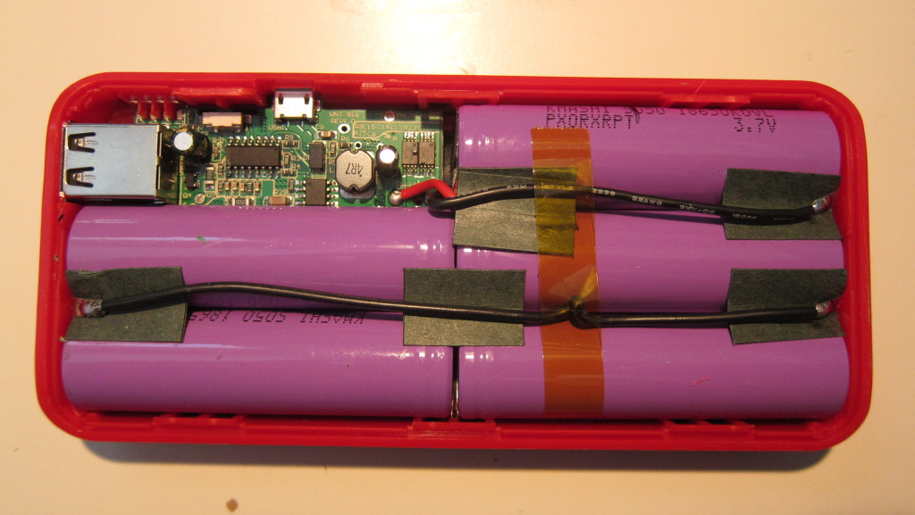
IMG_5700This is what I found inside. As you’d expect, a good portion of the volume is taken up by the batteries, five cylindrical 18650-sized lithium ion cells. This is the reason for the size and weight of the device. First off, the cylindrical cells don’t pack together as tightly as flat-pack pouch cells found in most phones, tablets, and higher end USB battery packs. Second, their steel walled container weighs more than the plastic membrane used on flat pouch cells.

The bigger issue though is that there are five of them, which means that they must each have a capacity of only 2,000 mAh. That’s not much. 18650 cells (which stands for 18mm diameter, 65.mm length) are widely used for laptops, battery powered tools, and even Tesla automobiles. I pulled some 18650 cells out of ~5 year old laptop battery packs that are rated for 2,600 mAh and still deliver ~2,550 mAh. More recent laptops use cells with 3,000, 3,200, or perhaps even 3,400 mAh capacity, so it would be possible to build a power bank of equivalent capacity with four, or as few as three cells, with a corresponding reduction of weight and size.

On the other hand, those larger capacity cells from Panasonic, Samsung, Sony, and others, retail for $6-8/cell, and 2,600 mAh cells go for ~$3-3.50. I am sure these cells were much much cheaper.

IMG_5701


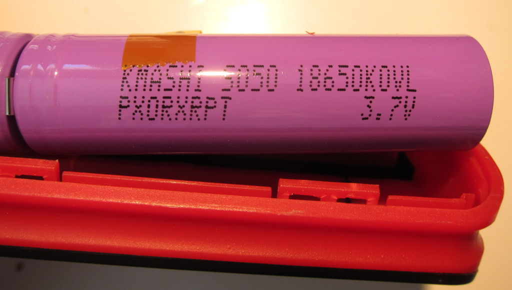
The cell wrappers are labeled “KMASHI SO50 18650KOVL PXORXRPT 3.7V,” This doesn’t give much of a clue as to the true origin of these cells. KMASHI doesn’t appear to be an actual battery manufacturer, that comes up in other contexts. 3.7V is the typical voltage for lithium ion cells, and 18650 is a common form factor, but searches for any of the terms on the label doesn’t produce useful results. I could cut the wrap off and see if there are any clues printed on the metal, but then I’d have to rewrap the cell, which would be a pain since they are all welded together.

So, who knows what kind of cells these are, they might even be reused used cells, for all I know.

IMG_5702

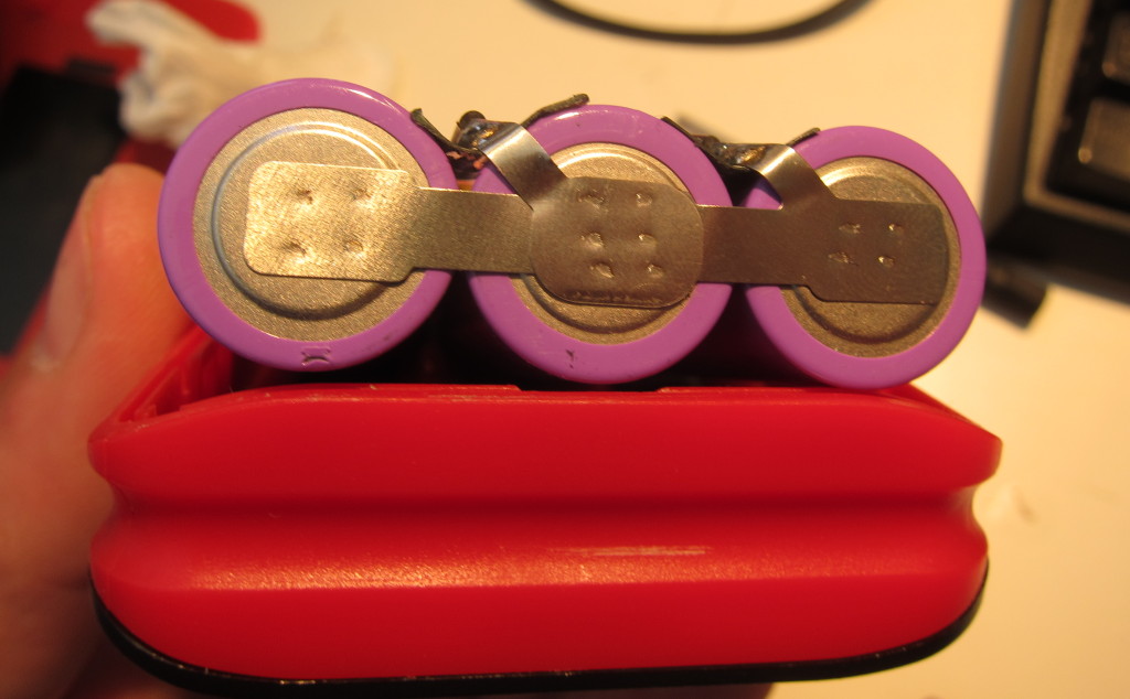
This photo shows that the cells have been spot welded together in a parallel configuration, which is commonplace in multi-cell USB battery packs. I suspect the parallel approach is typically used for a few reasons. First, it should be more tolerant of lower quality cells than the series-configuration. Second, it should pose less of a risk of frying the USB device if the voltage regulation circuit is funky. Finally, it makes it easier to charge the pack off of a USB power adapter.

Looking at the end of these cells gives another hint that these may be reused cells. From my experience, raised bottoms are unusual on 18650 batteries, and others have reported that they are often used to hide the evidence of old welds on cells that have been pulled out of assembled battery packs.

If they are reused cells, that causes me some concern. If they are good quality cells from battery packs that just sat on the shelf (aka New Old Stock), then it would be a non-issue as I have obtained cells that way myself. If they’ve actually been used, or if they are from very old packs though, thats a problem, as they could fail prematurely, and failing lithium ion batteries can be dangerous.

IMG_5699


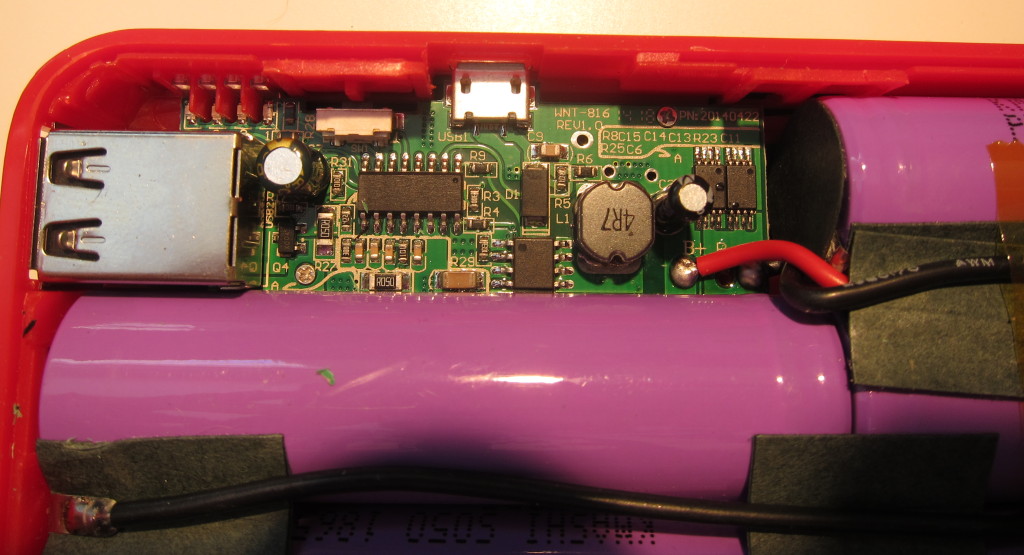
For completeness, I give you the printed circuit board, which is labeled as “WNT-816 Rev 1.0” and “PN:20140422” on the top. I can’t say much about the components. The two largest chips appear to have been sanded to obscure their origins. There are two other chips that have their markings which read “FS8205A,” near as I can tell, they are used for managing the discharge of lithium-ion batteries.That, and the inductor is solid-core, unlike the many hollow-core inductors I’ve seen on the powerbank PCBs they sell on Fasttech.

IMG_5705

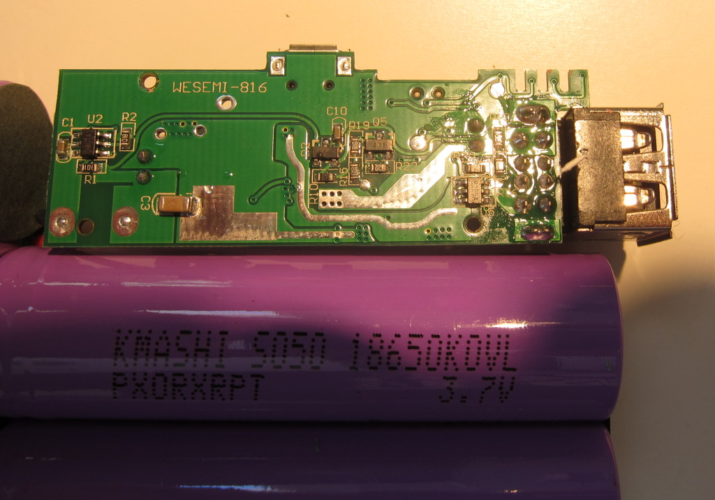
On the bottom, it is labeled “wesemi-816.”

I reassembled it and I’ve used it since taking it apart. It works pretty much as expected. I’ll post an update in a few weeks once I get some stuff I ordered for testing USB power sources.

Lenmar and NuPower MacBook Pro Battery Pack Teardown

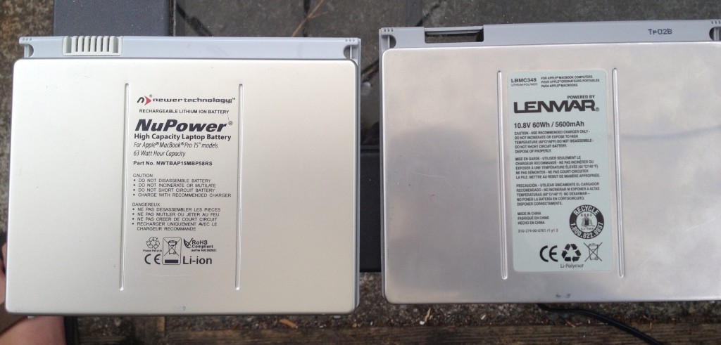
Today I took apart two different 3rd party battery packs for the 2006-2008  15″ MacBook Pro. The OEM batteries had the following model numbers A1175, MA348, MA348G/A, MA348J/A, MA348*/A.

These packs probably date from early 2010.

NuPower and Lenmar batteries

NuPower and Lenmar batteries

The first is a Newer Technology NuPower 63Watt Hour Capacity Battery, part # NWTBAP15MBP58RS. There is a barcoded sticker on the outside with the number U091228A11753.

The second is a Lenmar, 10.8v, 60WH/5600 mAh. Model/Part LBMC348.

Superficially they look very similar, but their are some significant differences in their construction.

The NuPower has a relatively thick aluminum plate on the outer surface that is glued to the case. If I recall correctly, this glue failed prematurely and had to be redone. The bottom section of the battery pack is a single piece of plastic, though the back side is painted with a metallic paint to simulate the appearance of the original Apple battery. While this would seem to be a reasonable construction approach, one has to wonder why Apple chose to use a metal back in the first place. A metal back would be thinner than a plastic back, and also transfer heat more readily.

The Lenmar uses a thinner sheet of aluminum for its outer plate. This plate is then adhered to a thin steel sheet that has various bent tabs which catch and latch into the plastic frame of the bottom case. The plastic frame is then glued to a thin steel tray. This is closer to the construction of the original Apple battery pack

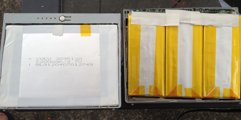
Internal view of NuPower and Lenmar battery packs

Internal view of NuPower and Lenmar battery packs

Once inside, we see a more significant difference in the construction of the two battery packs.

5,600 mAh Lithum polymer pouch cells in NuPower battery pack

5,600 mAh Lithum polymer pouch cells in NuPower battery pack

Cells from Lenmar battery pack

Cells from Lenmar battery pack

The NuPower pack, on the left, has a single stack of three 3.7v 5,200 mAh cells. They are labeled as Yoku 3895130, 5,200 mAh/3.7v, BL9120407012749. They measure ~130x95mm and the stack of three is ~11.25mm thick.

The Lenmar pack, on the right, has 3 stacks of pouch cells, each stack is 2 cells deep, connected in parallel. They are labled as YLE 3.7v, ICS594395A280 468061801483. Each pair of cells is ~90x42mm and is also ~11.25mm thick.

I don’t have an original Apple battery around to use in a close comparison, but the Lenmar battery pack construction is much closer to my memory of the stock Apple battery, both in terms of cell configuration, and assembly. I’m still not sure what to make of the absence of a metal back on the NuPower battery. I thought perhaps the Apple and LenMar batteries used the metal back to accommodate a slightly thicker battery, but that doesn’t seem to be the case, since the thickness of the cells in both the Lenmar and NuPower packs is 11.25mm. I don’t know how thick the cells are in an original Apple battery, but I suspect that the metal is there for better heat transfer, and its omission seems like an undesirable bit of cost cutting.

Looking more closely at the cells, I see that Yoku is a battery manufacturer based in Fujian, China. I’m going to guess that the “3895130” gives the dimensions of the cell, 3.8x x95x130mm, which pretty much matches with the dimensions I measured. I don’t know what the remaining number is, but my guess is that it is a manufacturing lot code.

YLE is manufacturer based in Shenzen, China. and ICS594395A280 is a documented part number for a 5.9x43x95mm 2,800 mAh/3.7v cell.

Interesting that the nominal capacity of the Lenmar cells are higher than the cells used in the NuPower, but NuPower claims theirs is a 63 Watt-hour battery, while Lenmar only claims 60 Wh. At this distance though, what I know is that the Lenmar pack is well and truly dead. Two of the parallel packs had voltages ~1v, which is dangerously low. The remaining pair of cells was ~2.6v, which might still be safe to use, though I’d have to put it through testing to see how much of the rated capacity remains. The NuPower still works, and the cells were at something close to 3.7v each. The estimated capacity of the pack, as reported by System Information, is quite low though, perhaps 50% of original, which is why I decided to tear it open in the first place.

I’m not sure what I’m going to do next, other than recycling the low cells. I’ll probably set the good cells aside until I get a hobby charger that I can use to analyze them and decide whether they are worth keeping to power misc projects.

I’m also going to look into buying replacement cells and rebuilding the packs, provided that the price is right and the seller is reputable. I could just order a replacement for the whole pack, but I’d be a bit concerned about getting old stock at this late date.

My not-so-inexpensive mini-ITX home storage server build

IMG_5779I wrote about the tortuous path I took to building a new home server in an earlier post. Now I’m actually going to take the opportunity to document the build.

First off, the parts list:

My goal was to have an inexpensive, capable, efficient, compact machine to run as a home server as an upgrade to some older Marvel Kirkwood based servers I have. Intel’s BayTrail Celeron CPUs were an interesting option, but I chose to go with an AMD Kabini APU, for a few reasons. Formost among them, it was available as part of a $100 bundle with a case and a motherboard with four 6Gbps SATA channels, rather than the two common on BayTrail boards.

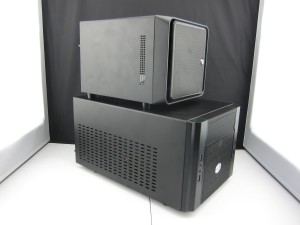
Norco S4-ITX case (top) compared to Coolermaster Elite 130

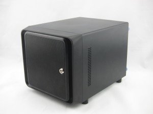
Unfortunately, the Cooler Master Elite 130 case in the bundle was bigger than I really wanted, so I ended up spending another $100 to get a Norco ITX-S4.

Unfortunately, the ITX-S4 required further upgrades and part-swapping.  The stock fan was amazingly loud at full speed, and because it was a 3-pin fan, couldn’t be regulated by my motherboard, so it was loud all the time. I ended up replacing it was a Arctic F8 PWM fan. The new fan is quieter, at full speed, and I set up a custom fan profile in the motherboard BIOS so it spends most of its time turning even more slowly and quietly.

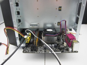
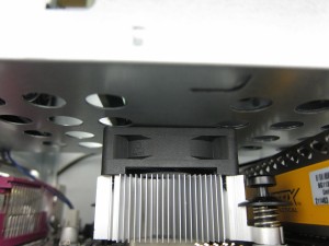
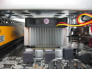
IMG_5578 IMG_5580A bigger issue is that there wasn’t enough clearance between the stock CPU fan and the bottom of the hard drive cage, which made it impossible to install the motherboard.

I was able to fit it in by removing the hard drive cage, but this resulted in about 1mm of clearance between the top of the can and the bottom of the drive cage.

I considered many options. The AM1 platform used by the socketed Kabini chips like the Sempron I used is still relatively new, and its a low cost platform, so 3rd parties haven’t been rushing to produce aftermarket heatsinks. I looked at the possibility of modifying a heatsink intended for another application, and considered grinding 5mm off the stock heatsink.

IMG_5769I finally realized that the stock fan was 15mm thick, and so I fitted a 10mm fan instead. Cheap and easy, so I did it. This seems to work pretty well, but I’m considering either cutting a hole in the bottom of the drive cage to improve airflow, a wider, lower-profile heatsink with a larger fan, or making some sort of baffle to improve airflow so I can keep the chip cool at lower quieter fan speeds.

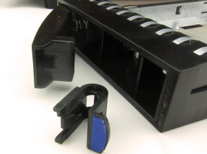
Overall, I’m going to have to give mixed marks to the ITX-S4 case. I like the size, and the looks, but there are a number of downsides. In addition to the noisy stock fan, the build-quality is kind of mixed. The sides bow a bit, but the biggest issue is the drive trays. The latching levers feel a little flimsy. I worry I’m going to break something when I insert or remove them.

IMG_5752Even worse, the latches that are supposed to hold the levers closed keep slipping free of the levers. This has happened at least once to each of the four drive trays. If it happens again I’m going to need to resort to some superglue.  This is completely unacceptable for a $100 case!


A few more notes on things that didn’t work out as expected. I purchased an IO Crest 2 Port SATA III PCI-Express x1 Card so that I had an extra SATA channel available to take advantage of an internal SSD bracket, saving the drive bays for 3.5″ drives. Unfortunately, the machine resets during the linux boot process, shortly after identifying devices connected to the card, so I’ve set it aside for now.

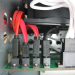
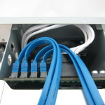
I also tried Rosewill 19.7″ Serial ATA III Blue Round Cables, thinking that the round cables would be easier to route. They weren’t. First off, I missed the fact that the ones I bought have 90° connectors on one end, which doesn’t work given the configuration of ports in the drive cage.  In addition, the 180° connectors were too thick for the close spaced SATA ports on the the motherboard. Moreover, the cables were still quite thick and stiff. I found it easier to use standard flat SATA cables. Some of the ones I had on hand were a tight fit because of the length of the molded connectors, so I picked up some matching cables with shorter connectors.

IMG_5732IMG_5740


Overall, I’m pretty happy with the way the project turned out so far. With a 3.5″ Western Digital Green HDD, two surplus laptop drives (one 7,200 RPM the other 5,400), and the SSD, it idles at about 25W. With cpuminer and sgminer mining litecoins on the CPU and GPU, respectively, it uses ~45W. At full-load on a warm day the fans are a little noisy, in particular, the CPU fan has to spin at nearly full speed, (4,500 RPM), to keep it under 60°C, otherwise the CPUs thermal throttling will kick in, which seems to shave ~5W off the load by dropping the CPU and GPU clocks by 20% or so.

Next step is to install Debian and migrate over data and services from my old server. In the longer run, I may revise this build with a BayTrail build for lower power consumption and noise.