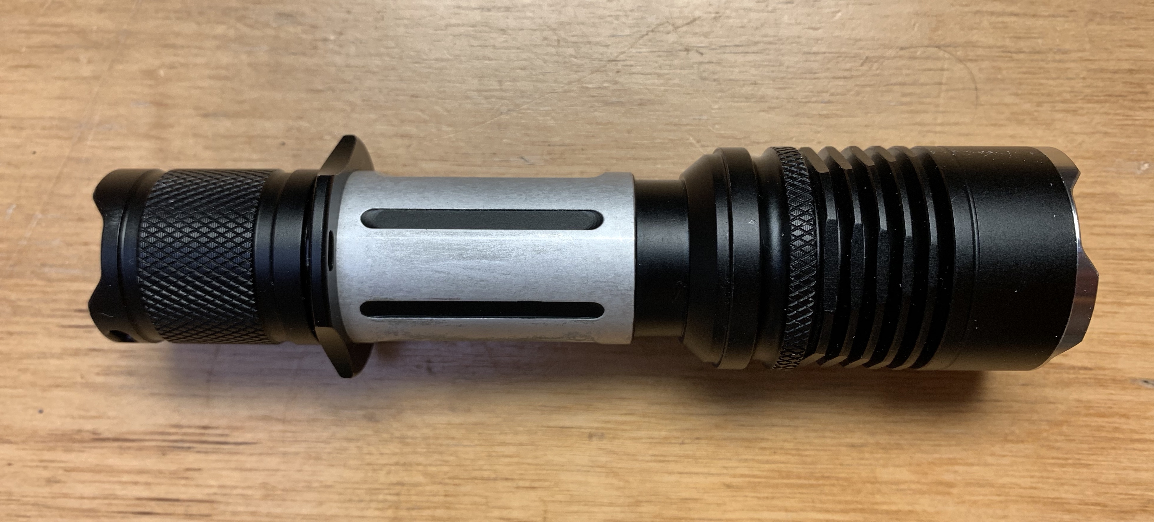
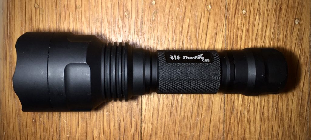
I’ve been looking for an inexpensive way to build a compact, high-output (>2500lm) flashlight. This post documents a successful result.
There are two straightforward routes to a high-output flashlight. The first is to use a high-output emitters like the Cree XHP70.2. The second is to use multiple (often three or four) lower output emitters.
The downside of high-output emitters is a combination of expense and limited choices for both driver and emitter. The emitters themselves aren’t badly priced when considering power/$, but they typically require a 6v power-source, which requires either a high powered boost driver, or two batteries in series, requiring a larger host. In addition, there are fewer choices for CCT, tint, and high-CRI among high-power emitters.
Multi-emitter configurations are commonly configured with the emitters in parallel, meaning they can be powered with a single cell controlled by a wide-range of drivers. In addition, they can most of the 3v emitters on the market, in any combination your heart desires. The downside is that they generally require specialized MCPCBs, which must be pared with optics or reflectors with matching spacing. These reflectors and optics are shorter than the single reflectors most hosts are built for, so they either need custom spacers, or a specially built host.
My project has the advantage of working in a variety of single-emitter hosts with minimal modifications, while allowing the use of 3v drivers and a wide array of emitters.
Ingredients:
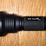
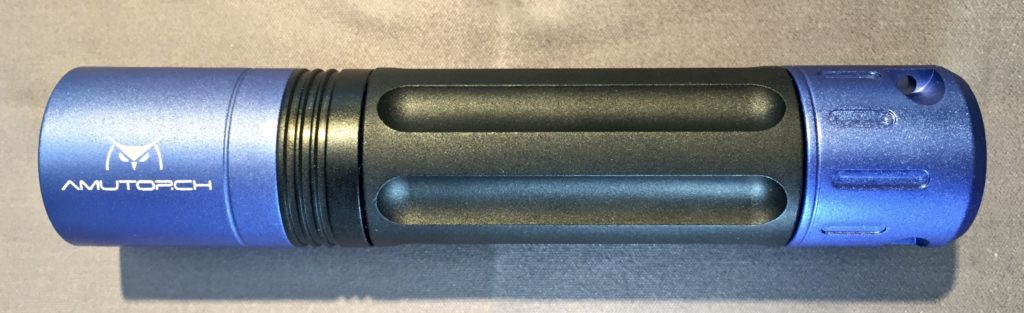
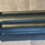
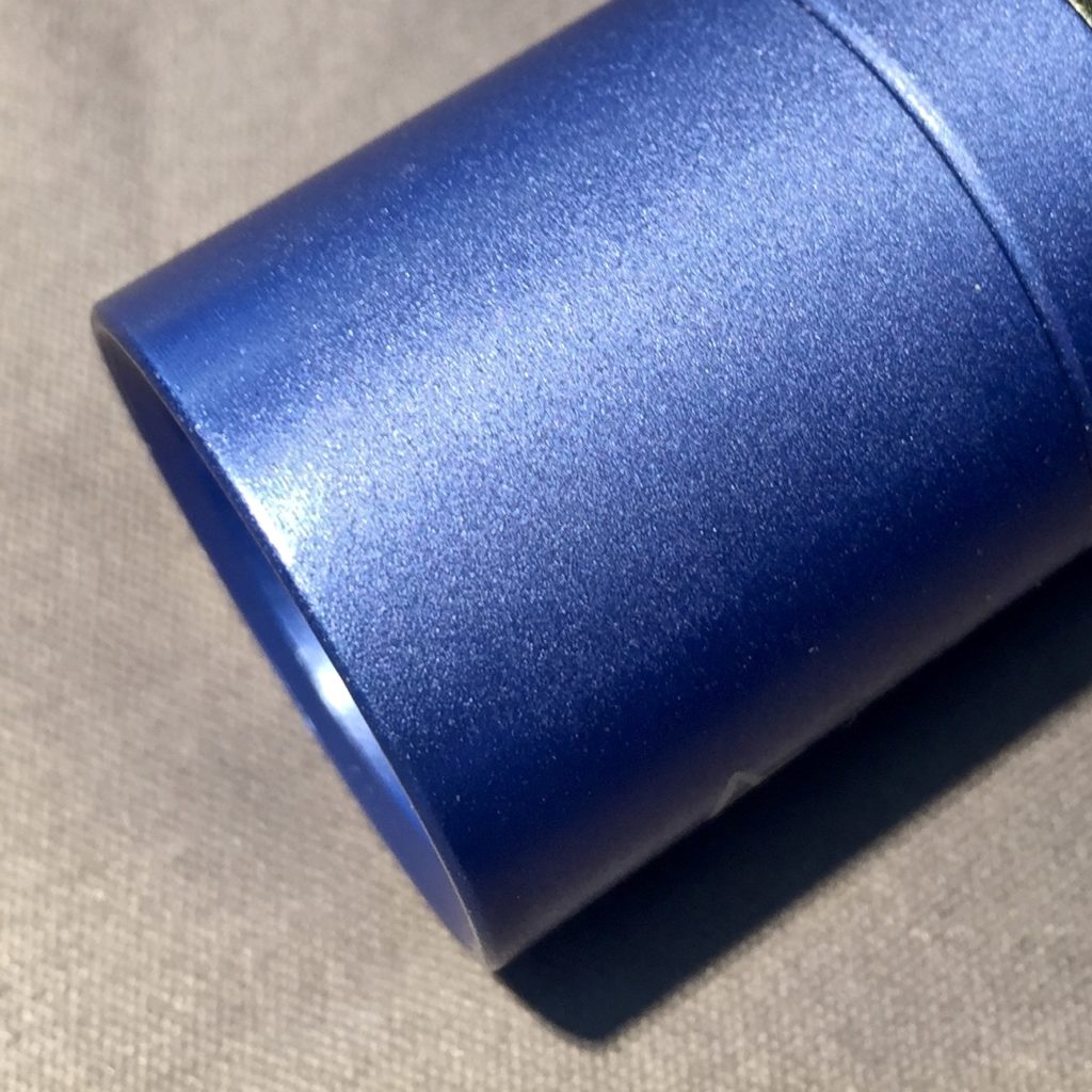
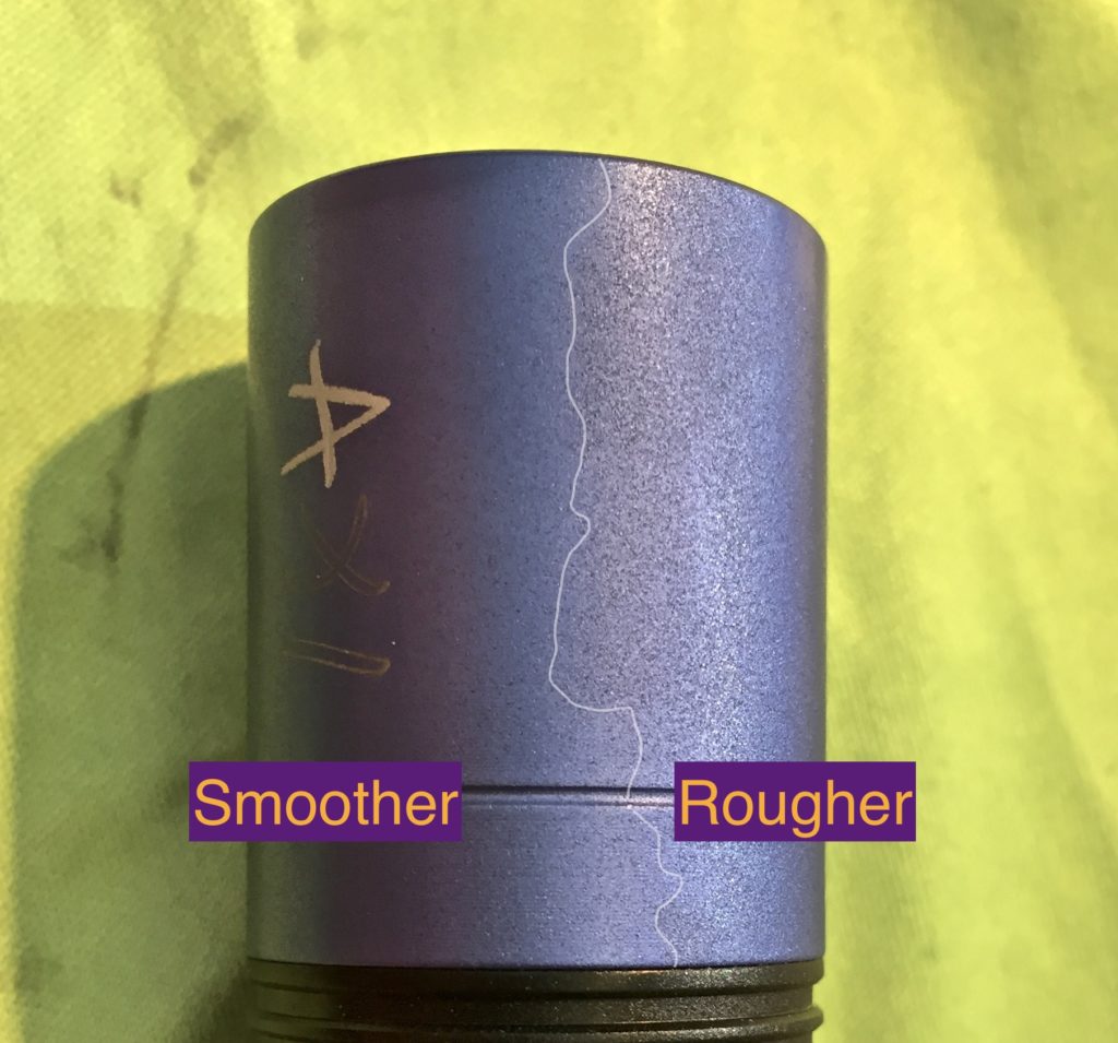
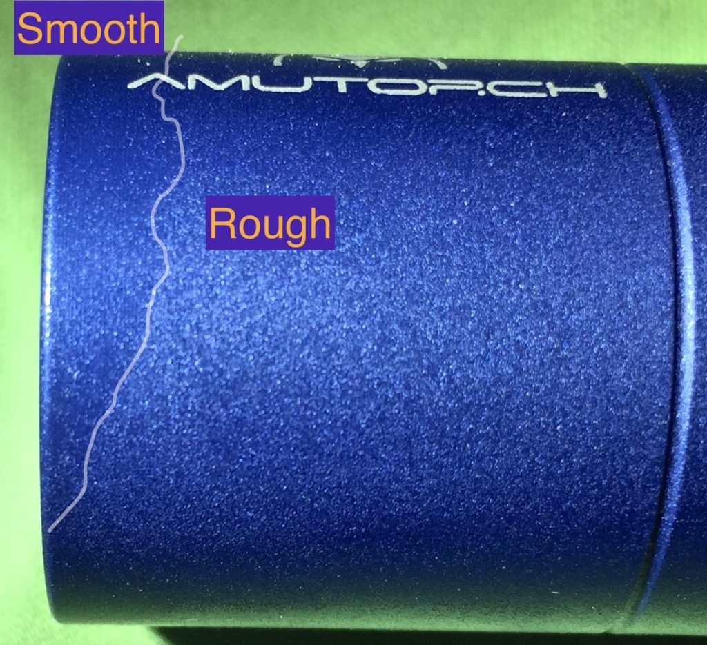
- One Thorfire C8s
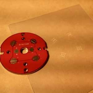
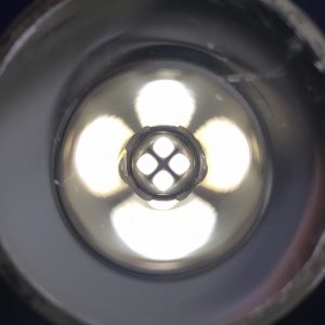
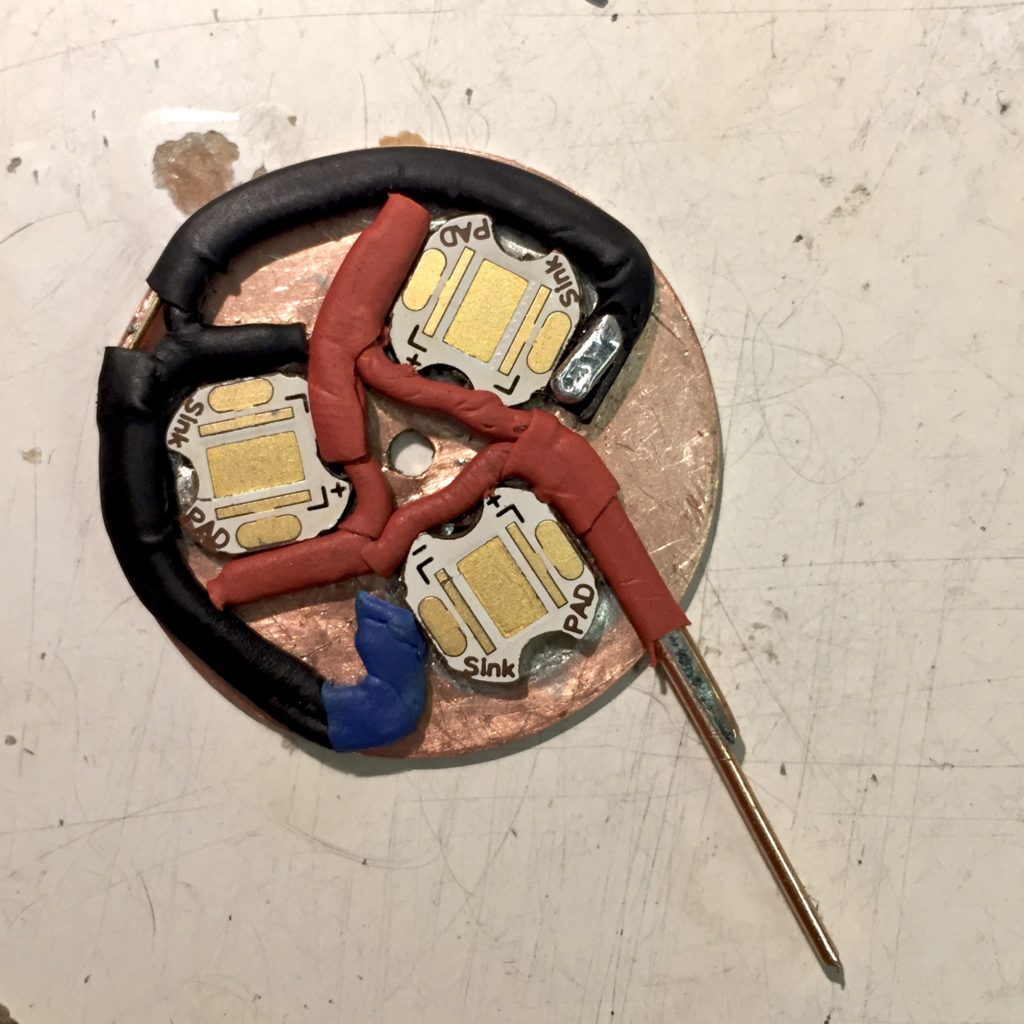
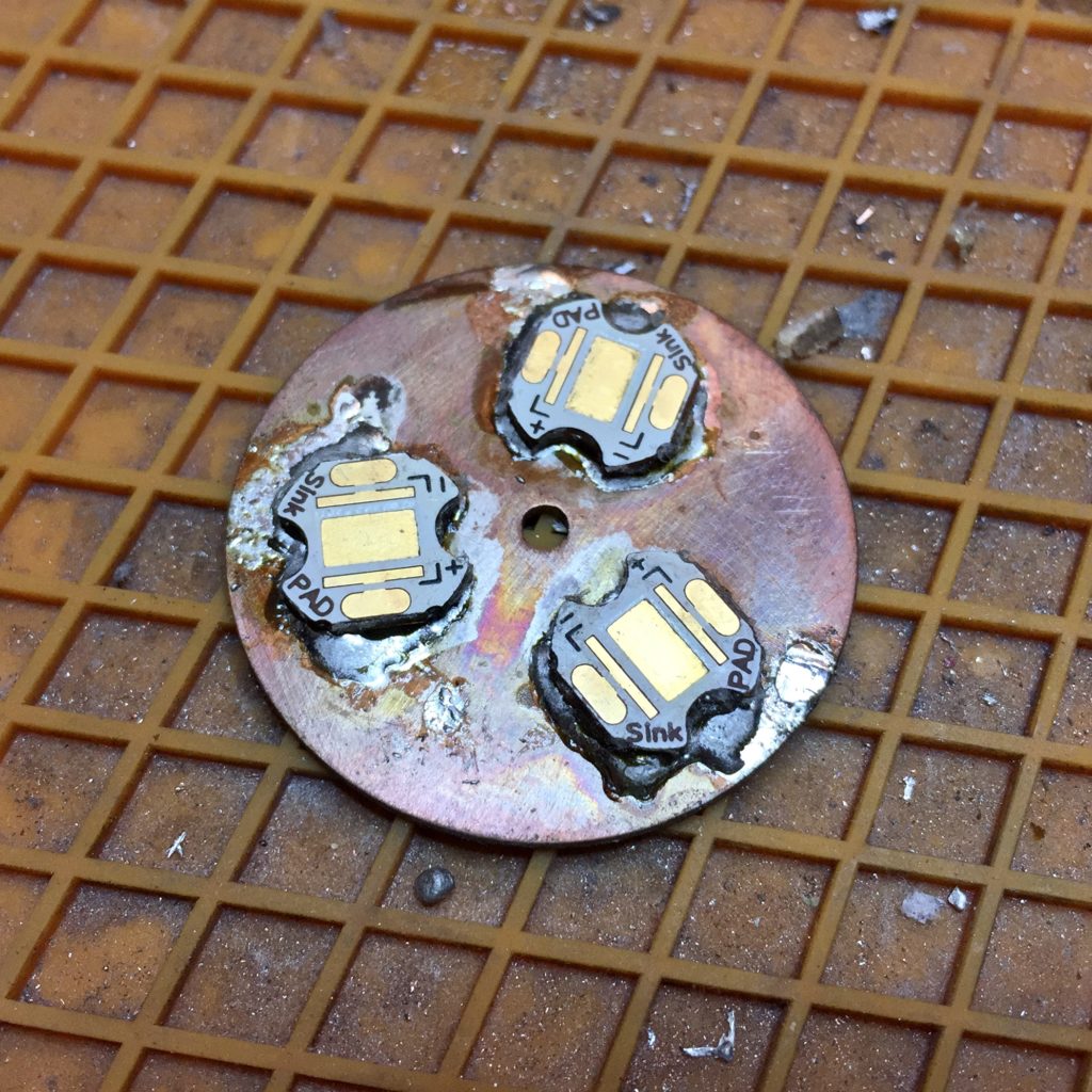
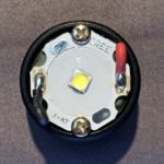
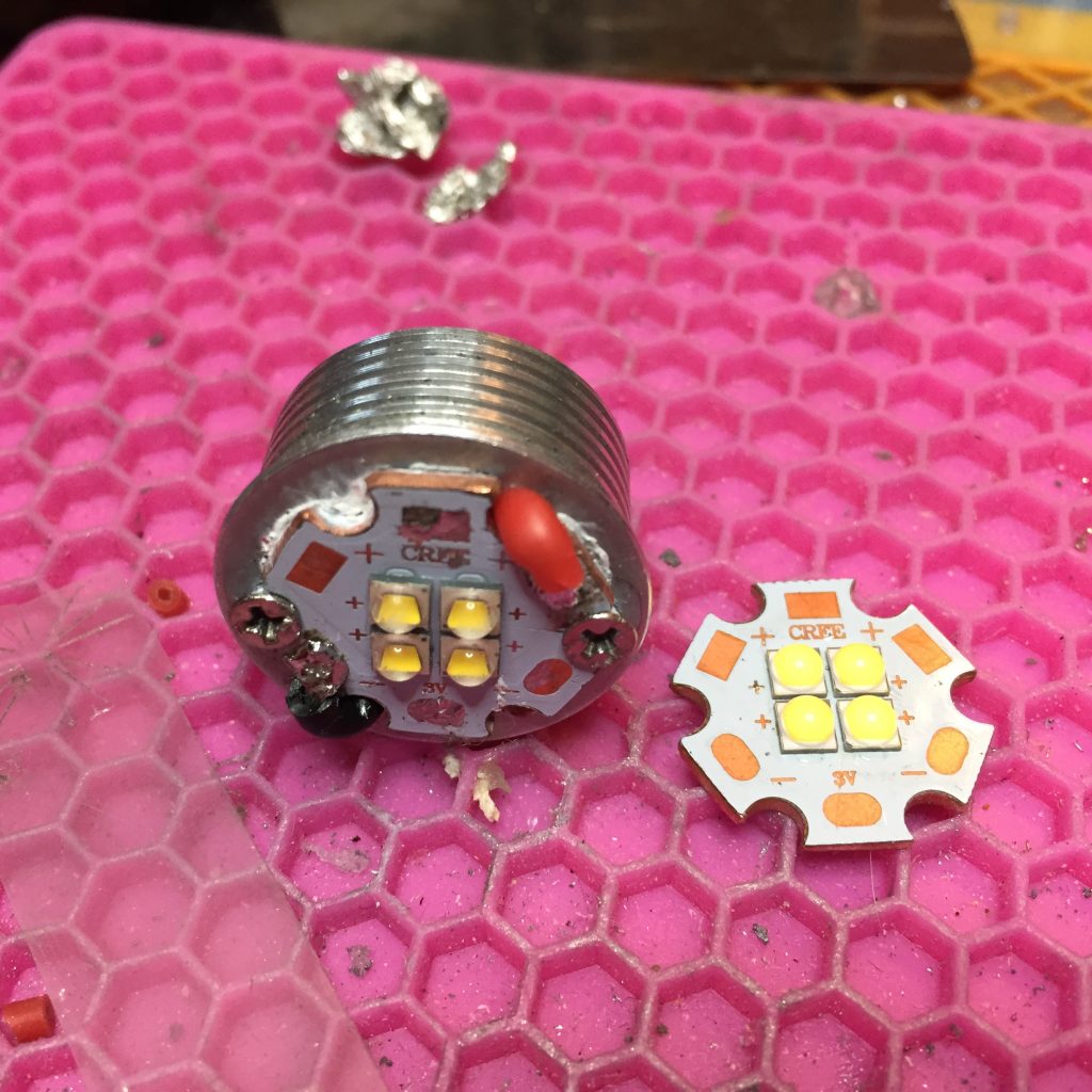
- Four warm white XP-G2 of unknown flux binning…
- Mounted in a 2×2 array on a direct thermal path copper MCPCB which electrically connected them in parallel
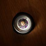
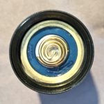
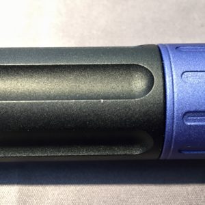
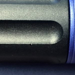
- DCfix diffusion film
- Lexel’s 17mm version of the TA v1 driver.
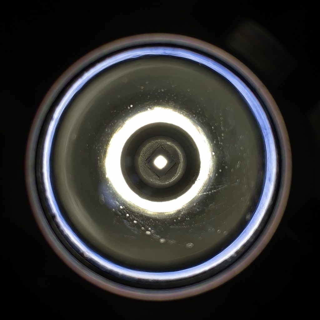
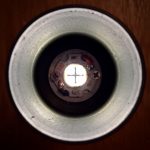
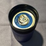
For my first pass, I used an orange peel reflector I had on hand in the hope that it would, on its own, blend the beam enough to eliminate a dark spot in the center caused by the gaps between the emitters.
When that didn’t work, I used some diffusion film, which worked really well, well enough that I decided to try the original reflector. The film was still enough to blend the beam enough to remove the dark spot in the center of the beam.
The end result is bright and quite floody. I don’t have a great way to measure the brightess or intesity, but I’d guess that its less bright than my BLF Q8 and brighter than the 3x Nichia 319a emiters I put into a Sofirn C8F
I still have more of the MCPCBs, I’d like to try another build, but I’m not sue what emitters to use. I want more power, and also higher CRI.
Update 2018-09-02:
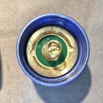
I got a UNI-T UT201-E clamp meter last week and rigged up a modified tail board so I can measure the current draw of flashlights. I wanted to approximate the electrical characteristics of an actual flashlight, so I used a standard tail-switch board, with a bypassed tailspring. I attatched 13AWG wire so I have a loop I can use to measure the current with the clamp meeter. I also put a standard Omten 1288 switch in line, to reproduce switch resistance. With fully charged, high-drain cells, I got a peak of about 11A. Not bad, but I wanted more.
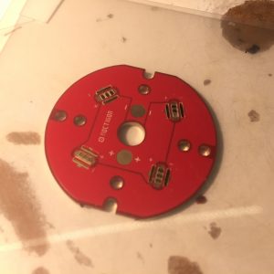
After studying datasheets and independent tests, I decided to use some 90 CRI Samsung LH351D emitters I bought recently. By my estimates, they’d peak at ~4A each (16A) total, and produce a peak of ~1200lm each, for a total of 4800 lumens, peak (out the front lumens will be lower). Not bad for a 90CRI light.
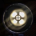
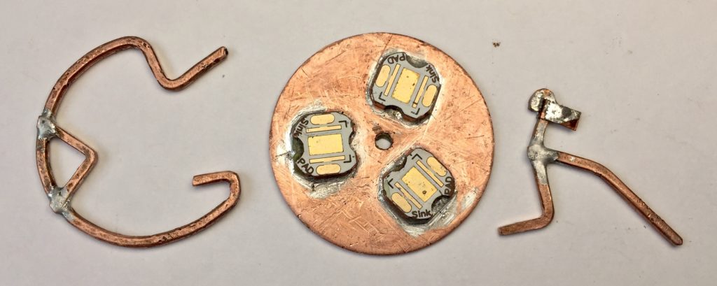
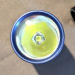
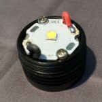
I have 5000K emitters (PN: SPHWHTL3DA0GF4RTS6) and 4000K emitters (PN unknown). I decided to use two of each. I reflowed them on to an empty 2×2 emitter MCPCB that I’d lapped for better contact with the emitter shelf. Once I had the light back together, I did more tests.
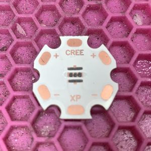
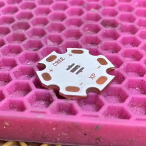
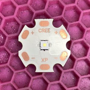
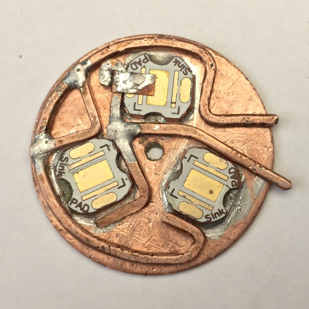
XP-G2 (left), LH351D (right)
I’m happy to say, my estimates were pretty good. With a Sony VTC5A, the peak current draw was over 18A. With Samsung 30Q or LG HG2, the peak current was ~17A. I don’t have way to measure output, but I’d assume those numbers are on track too.
Not surprisingly, the light heats up very quickly on full power.
-
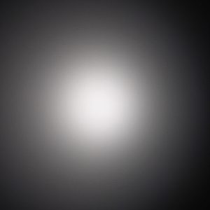
-
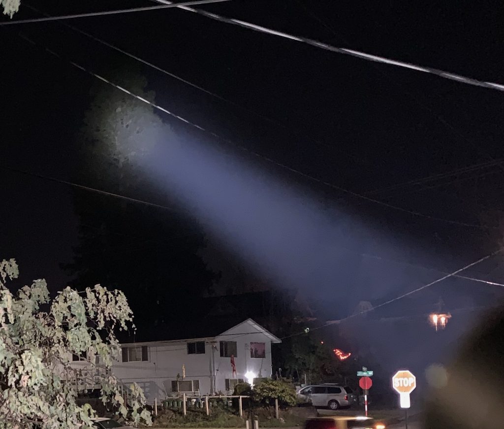
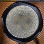
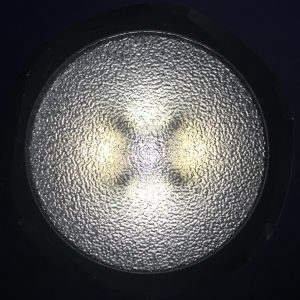
~4′ from surface
-
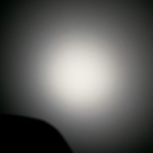
-
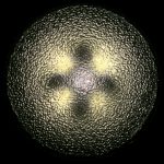
~8″ from surface
To give some sense of beam uniformity, I took a couple shots at different distances against blank surfaces. Don’t compare the color between shots, the surfaces are different shades of off-white, but the color uniformity in each shot should be useful.