HP 6177C DC Current Source Troubleshooting/Repair

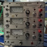
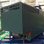
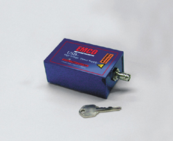
I picked up a Hewlett Packard 6177C DC Current Source on ebay for less than $75 shipped. This is a precision constant-current source that can deliver 0-500mA at up to 50V.

IMG_7318
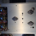
The seller described the unit as used with responsive controls and indicators. When I received it, I could see that while in generally good physical shape the upper right portion of the front panel was more bent/buckled than I could make out in the eBay photos.

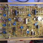
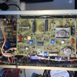
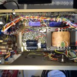
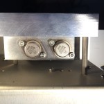
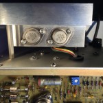
So, first thing I did was partially disassemble the unit to fix the front panel.

Once I got it back together, I did some quick functional tests and found that the current output was consistently 1/10th the expected value. In the 500mA range with the current pot set to maximum, it produces a max of 53mA of current, on the 50mA range, it produces 5.3mA, and on the 5mA range, 0.53mA. This behavior doesn’t vary noticeably between shorting the outputs and having a 30 Ohm load. With a suitably high resistance, the voltage will hit >50v, provided the current doesn’t exceed ~50mA.

So, next step was to look at the service manual and work through the troubleshooting steps.

First thing is to check some voltage rails.  These all checked out, though a few were out of spec on ripple.

Next is to go through the problem isolation procedure, which starts with checking the guard voltage to see if it varies between 0 and -1V. Nope! In each range it maxes out at… ~100mV, or 1/10th of the expected value. Notice a pattern forming?

I started to work through the guard supply troubleshooting instructions, but I got hung up. After disabling the main supply, as instructed and checking a few voltages, it wasn’t clear to me whether I should go immediately through the subsequent steps, or reverse the change and proceed from there. Subsequent instructions just raised more questions.

I asked for guidance in the EEVBlog forum, and while waiting for a response, worked to better acquaint myself with the schematic and theory of operation of the device.

I’m still not sure what to do, and rather than pushing forward, I realize that I already have other incomplete projects that need my attention, I’ve gathered everything up into a bin and put this one on the shelf, for now.


Dismal Ebay AVR DDS Signal Generator

Months ago, I bought a $15 AVR-based DDS signal generator kit from eBay. I didn’t have high expectations, but I thought it would give me a capability I didn’t currently have, and give me the chance to practice soldering.

It was immediately clear upon opening the package that it was at least half a failure, because it was fully assembled. For this, I got a partial refund, making it a ~$10 fully-assembled DDS signal generator.

It sat a few months while I acquired, refurbished, diagnosed, and ultimately repaired a used Power Designs TP340A three output bench power supply that I could use to provide the +15, -15 and +5V needed to power it.

Once I had it powered up and hooked to the scope, it took me 5-10 minutes to figure out how the thing worked. The digital controls are a little odd, but easy to figure out. The outputs and analog controls are a little fussier. Ultimately though, I figured out that the leftmost BNC is for a high-speed square-wave output. The right BNC is for the synthesized DSS output, the leftmost potentiometer is for amplitude, the right for DC offset.

IMG_8201

It didn’t take too much longer to see how badly this thing sucks. At first glance the 2 KHz  sine wave doesn’t look too bad

DS1Z_QuickPrint34If you look closely though, you see some consistent glitches. This thing generates an analog value by switching resistors using the AVRs GPIO pins. My guess is that this glitch is caused by one or more out of tolerance resistors.

DS1Z_QuickPrint33

Looking even more closely, you can start to see high-frequency noise. In his Youtube review (embedded below), Electron Update notes that this noise has a frequency of 1MHz and believes that this is probably noise from the digital section.
DS1Z_QuickPrint46

The 2KHz square wave isn’t too great. The rise and fall times are rather significant relative to the on/off times.

DS1Z_QuickPrint45

At 20KHz, the square wave is a sloppy triangle. Note too that the peak-to-peak amplitude is only 6.56v vs the 18.2 it delivers at 2Khz.

DS1Z_QuickPrint41

The “high speed” 20KHz sine isn’t very good either. The waveform is nearly identical to that of the 20KHz square wave, and like the square wave, the peak-to-peak voltage of ~6.6v is a fraction of the 17.8v excursion at 2KHz.

Of course, 20KHz isn’t really high-speed at all. Its at the top end of the human auditory range. The device actually supports up to ~65KHz. It doesn’t get better.  The truth is, the waveforms go to hell before 10KHz.

IMG_8201

My device seems to be based on the AVR DDS signal generator V2.0 software and hardware from 2008, with minor revisions to the hardware for manufacturability.

Electron Update did a review/analysis of a similar device based on the same design on his youtube channel.

The design has some fundamental limitations, thought it isn’t clear if some of my problems are specific to my unit.


Power Designs TP340A Repair/Refurb

I picked up an old Power Designs TP340A bench power supply on eBay. The TP340A is a three channel (or “source) power supply. Source A & B have identical specs, providing up to 1A from 0-32v DC. They can be operated independently, or in tracking mode to provide positive and negative voltages. The third source only covers from 0-15v, but can deliver 5A at up to 6V and 2A at up to 15V. I bought it to power projects as I teach myself more about electronics. Little did I know what I was in for.

It showed up well-packed in great physical shape. There were a few scuff marks on the case where it had probably been pushed up against another piece of equipment, and some stickers and a few scuffs on the face plate, but otherwise, it looked nearly new.

When I took it apart, I found the insides were in similar condition.

On closer inspection though, I noticed something that wasn’t quite right

Bad C104 is Bad

The 100 uF 25V Sprague electrolytic capacitor in postion C104 looked like it had a bad inner seal. I decided not to power up the PSU until I’d replaced this cap.

The other two channels have the same type of capacitor in the same position in the circuit. They looked Ok, but I decided they should be replaced too, and while I was at it, I figured I’d also order replacements for the other big electrolytic caps. This decision proved to be a mixed bag.

The visually intact sibling 100 uF Sprague caps proved dead when I tested them after replacing them. On the other hand, the other electrolytics were still in spec. Which is more than can be said about some of their replacements.

After replacing all the caps, I powered things up and was greeted by a wretched buzzing metallic groan . I quickly switched the power off and gathered my wits, such as they were. Then I turned it on again for long enough to twiddle some of the knobs, things still weren’t right, but I had slightly more information. I switched it off again, thought for a minute, and switched it on again. This time the horible groan was joined by a ffffffssstPOPffffff. I switched it off, but there was another ffffffssstPOPffffff. I’d put two of the capacitors in backwards and they’d vented.

I replaced the vented caps with the originals getting the polarity right this time, so I could see if I’d done the thing permanent harm. Happily, the horrid groaning sound didn’t return the next time I switched the power on. It didn’t work though.

It didn’t take long to find them problem, I’d turned the voltage and current limit knobs the wrong way. After correcting that problem, I found that all the channels of the supply were fully functional, though things didn’t seem quite right. In tracking mode, source B didn’t respond at all until the voltage was up to about 8V and then started dropping off as it was turned up past 16v.

I started going through the troubleshooting steps in a PDF copy I’d found of the operating manual, but that’s going to be the subject of another post.

Tektronix Mainframes

I’ve been looking into old Tektronix osciloscopes and related gear lately, and I thought I should write-up some of what I learned.

Last year, I posted a few installments in my saga of figuring out what to buy for my first osciloscope. I ended up with a Rigol DS1074Z, and while I haven’t gotten a lot of use out of it, yet, when I have used it, its saved me a lot of troubleshooting time.

Recently though, I’ve been looking for ways to address some of the limitations of my scope. In particular, I’d like to be able to do low-noise differential measurements on one or more channels. In part, this allows more flexibility in using all my scope channels to look at power supply circuits. It can also be useful for looking at power supply output noise and ripple.

One approach is to use the math function of the oscilloscope to calculate a differential between two of the input channels. This has its uses, but suffers from slow-update speeds and the fact that some of the signals I’m looking for are already at the limit of the DS1074z’s resolution.

Another approach is external differential probes. Unfortunately, these are expensive. New they start at $300 or so. Used are a little better, starting at $100, but most seem targeted at high-voltage rather than high-sensitivity use.

This brings me to the Tektronix gear. I’m less interested in the 7000 and 5000 series scopes themselves, than in all the various modular “plug-ins” (particularly high-sensitivity differential amplifiers) Tektronix developed for them. Tektronix also sold a line of stand-alone chassis called the TM500 and TM5000 series, and an accompanying line of plug-in modules.

Now, the first thing you need to know is something I was lucky to figure out before buying anything on ebay, which is that, while the plug-ins for the 7000 series, the 5000 series, and the TM500 and TM5000 series all appear to have superficially similar form-factors, they are incompatible. You can’t use a module intended for a scope in the stand-alone TM500 or TM5000, or vice-versa. Nor can you use a module for a 5000 series scope in a 7000 scope, or vice-versa. There are other important distinctions too.

Within the 5000-series of scopes and modules, there is a distinction between “slow” (~2MHz bandwidth) and “fast” (50MHz bandwidth). You can use slow modules in fast scopes, but you can’t use fast modules in slow scopes.

Within the 7000-series, which cover an even wider range of bandwidths from 25MHz all the way up to 1GHz, most scopes are compatible with most plug-ins, according to Tektronix.

For the stand-alone mainframes, modules for the TM500 will work in the TM5000, but the reverse isn’t always (usually?) true.

My inclination is to get a 4-slot stand-alone chassis like the TM504 to save space and minimize shipping costs. Unfortunately, it seems that the AM502 differential amplifier module is rather rare and relatively expensive. There is just one on eBay at the moment and only a few in the available history of past sales, and the prices seem to start at $100.

Meanwhile, there are multiple examples of the equivalent 7A22 or 5A22N modules for the 7000 and 5000 series scopes, with prices starting below $50. The necessary scope and chassis can be had for as little as $100 or so more, about 2x what a TM500 chassis might go for, with the downside of added shipping costs and the (possible) upside of a second scope. Moreover, there are apparently pass-thru outputs so would still have the option of using any modules I acquire with my existing digital scope. I’m also interested in other modules, like function generators.

The smartest thing, at this point, would be to put this project on hold and finish up the half-dozen Keithley 197A multimeters I’m in the process of restoring and repairing, or the Power Designs TP340A I’m in the middle of fixing (destroying?). If wisdom prevails, I’ll have this post to remind me of what I’ve learned, should I ever come back to the idea of buying some old Tek modules.

To that end, here are some of the resources I found useful in researching this:

USBHV, because why not have a USB-powered 2000V source?

In the last 5 years or so, USB has emerged as THE standard power source for portable electronics, and a host of other low powered devices.

GNEMCO_05Today, I happened to stumble upon an early example called the USBHV on eBay. The USBHV is a USB powered high-voltage source from EMCO High Voltage, released in 2009. The USBHV was positioned as a compact, USB-programmable (and powered) high-voltage source for research use. From what I’ve been able to tell, there was actually a line of products, differentiated by positive or negative voltage, and maximum voltage, with the option of 200V,  500V, 1000V, 1250V and 2000V at up to 1W of output (USB can deliver 2.5W). My guess is that they had a board with a USB controlled AD/AD converter for setting and reading back voltage, and mounted one of their standard high-voltage power modules.

The present-day EMCO High Voltage website only has one tiny reference to the product, a link to a generic form for information on off-catalog products, so no datasheets, manuals or software.

Keithley 2000 RS-232 Serial WTF

My Keithley 2000 DMM craps out during serial communications with a PC over RS-232.  When it does, the voltages on the TxD (yellow trace) and RxD (blue trace) lines look like this:

19.2kbps Fail KE

There are a few things wrong here.

  • The idle voltage of the RxD line should be -7v or so, similar to that of the TxD line, rather than the -1.7v it starts at.
  • The obvious decline in signal quality before the RxD locks at the ~1.2v shown at the end of the trace.
  • RxS locks at 1.2v, rather than returning to it’s idle voltage.

I came across someone who had trouble with the RS-232 level shifter IC on the similar Keithley 2015, so I carefully checked it out. It seems to be well under-spec on the output of its internal -10v power supply, which can only deliver a sustained 6mA. The +10v supply, on the other hand, can provide much more. I also diligently checking of voltages and current delivery of all the signal lines both the multimeter and the USB to RS-232 adapter its connected to.

It appears that the PC is trying to drive the RTS line to +7v. At the same time, the multimeter is trying to drive the RTS line down to -9v, and its loosing. As a result, it can’t drive the RxD line below -1.7v, and eventually, while transmitting, it gets stuck at +1.2v.

But why is the the DMM trying to do anything on the RTS line? That’s the job of the “data terminal equipment,” or DTE. I checked the reverse-engineered Keithley 2000 schematic, and it shows that the RTS line is connected to one of the transmit outputs of the level-shifter IC, something I confirmed by doing a continuity test. This makes no sense to me.

If I disconnect the DMM from the RTS line, everything seems to work fine. The DMM drives the RxD line to -9v at idle, and sustains signal quality throughout a transmission.

RxD is in much better shape when RTS isn't connectedI can’t imagine I’m the first person to come across this. I’m surprised though that I can’t find any mention of it online.

Update:

I posted about this in the EEVBlog Forums and a few users provided some details of similar issues they’ve had with RS-232 communications on the Keithley 2000 DMM. None of them have gone as deep as I have, but their descriptions are explained by my hypothesis.

I’m interested in whether later versions of the firmware leave the RST pin floating. So far no one with more recent firmware has checked for me, but one user remembers someone getting a similar problem fixed with a firmware update.

I’ll probably try doing a firmware update on my own. One user reports that he figured out he could use some Flash chips replace the EPROMs, which is attractive because I can re-use the chips and I don’t have to buy a legacy device like an EPROM programmer.

In the meantime, I picked up a straight-through male-to-female DB-9 cable and clipped off the RTS pin (#7). With it in place between the USB RS-232 adapter and the DMM, I ran a test querying the DMM with “*IDN?” every second for an hour or so. The DMM remained responsive for the whole time, and the responses it sent were complete, and uncorrupted. Previously things crapped out within a few minutes and only a few commands.

Update 2015-07-20:

I now have a unit from ~2007. It leaves the level of the RTS pin to the DTE, as it should. Upon closer inspection I found that the board has been revised so the RTS pin is no longer connected to the level shifter IC at all.

Fish8840 AVR Transistor Tester Review

Today, I’m looking at a neat gadget I got on ebay for about $20 called the “Big 12864 LCD Transistor Tester Capacitance ESR Meter Diode Triode MOS NPN LCR.”

There are hundreds of listing for dozens of variations of these under different names, for prices ranging from ~$12-40.  Most, if not all of them, are made in china. Most, if not all of them, are descended from the AVR Transistor Tester project by Markus Frejek (or google translated), with further improvements by Karl-Heinz Kübbeler (or google translated). Unforunately, none of the Chinese clones honor the projects license and release source-code for their firmware modifications. Fortunately, people are figuring out the hardware differences on some of them, and adding support for to the open source project. The english language documentation for the project is great. It actually includes information on some of the chineese clones. Even better, the design and documentation are a great example for learning how to make good use of the hardware on an AVR MCU.

The Fish8840 version I have, which has a PCB date of 2014-07, has stupid bug in the power-management circuitry which causes it to have excessive current drain when it is supposed to be “off.” This video review by George Thomas of AmateurLogic.tv includes a simple modification that fixes the problem.

I didn’t really love this one. In addition to the flaw described above, some of the graphics are hard to read. Plus, there are rumors that the hardware is locked to block installation of different firmware.

For more information: