AVR Transistor Kit and Case Mod

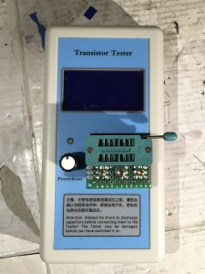
I ordered an AVR Transistor/component tester kit from Bangood. At the beginning of the year I bought AVR transistor tester by Fish8840 off of eBay and found it a bit lacking. This kit is better. It uses the 1.12k version of the open source firmware, and includes a rotary encoder for easier access to the advanced features. I also opted for the case.

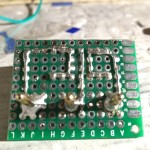
The kit makes use of through-hole components for easy home assembly. It includes an external 8MHz crystal, a voltage regulator, and uses narrow 1% and 0.1% tolerance resistors in critical positions for highest accuracy.

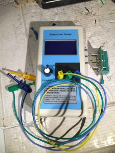
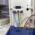
The case is designed to use a ceramic socket (provided) for connecting components, and also provides two banana jacks to allow test leads for testing larger components. People have complained that the provided socket is hard to use and doesn’t make good contact, and I wanted all three test connections available via leads, so I decided to modify the case.

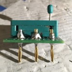
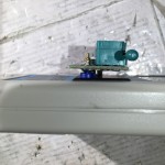
My modification is inspired by some of the fully assembled versions of the tester I’ve seen on ebay. I cut a piece of plastic and glued it over the existing holes for the socket and banana jacks on the case and drilled three holes for 2mm banana jacks I ordered on eBay. Then, I cut a piece of protoboard and drilled three holes for some 2mm  banana plugs, which I screwed into the board. Then I soldered in the ZIF socket and connected up the leads to the plugs.

I haven’t tried building the latest firmware from source for this, but my understanding is that “mega328_st7565_kit” is the proper version to build.

Dismal Ebay AVR DDS Signal Generator

Months ago, I bought a $15 AVR-based DDS signal generator kit from eBay. I didn’t have high expectations, but I thought it would give me a capability I didn’t currently have, and give me the chance to practice soldering.

It was immediately clear upon opening the package that it was at least half a failure, because it was fully assembled. For this, I got a partial refund, making it a ~$10 fully-assembled DDS signal generator.

It sat a few months while I acquired, refurbished, diagnosed, and ultimately repaired a used Power Designs TP340A three output bench power supply that I could use to provide the +15, -15 and +5V needed to power it.

Once I had it powered up and hooked to the scope, it took me 5-10 minutes to figure out how the thing worked. The digital controls are a little odd, but easy to figure out. The outputs and analog controls are a little fussier. Ultimately though, I figured out that the leftmost BNC is for a high-speed square-wave output. The right BNC is for the synthesized DSS output, the leftmost potentiometer is for amplitude, the right for DC offset.

IMG_8201

It didn’t take too much longer to see how badly this thing sucks. At first glance the 2 KHz  sine wave doesn’t look too bad

DS1Z_QuickPrint34If you look closely though, you see some consistent glitches. This thing generates an analog value by switching resistors using the AVRs GPIO pins. My guess is that this glitch is caused by one or more out of tolerance resistors.

DS1Z_QuickPrint33

Looking even more closely, you can start to see high-frequency noise. In his Youtube review (embedded below), Electron Update notes that this noise has a frequency of 1MHz and believes that this is probably noise from the digital section.
DS1Z_QuickPrint46

The 2KHz square wave isn’t too great. The rise and fall times are rather significant relative to the on/off times.

DS1Z_QuickPrint45

At 20KHz, the square wave is a sloppy triangle. Note too that the peak-to-peak amplitude is only 6.56v vs the 18.2 it delivers at 2Khz.

DS1Z_QuickPrint41

The “high speed” 20KHz sine isn’t very good either. The waveform is nearly identical to that of the 20KHz square wave, and like the square wave, the peak-to-peak voltage of ~6.6v is a fraction of the 17.8v excursion at 2KHz.

Of course, 20KHz isn’t really high-speed at all. Its at the top end of the human auditory range. The device actually supports up to ~65KHz. It doesn’t get better.  The truth is, the waveforms go to hell before 10KHz.

IMG_8201

My device seems to be based on the AVR DDS signal generator V2.0 software and hardware from 2008, with minor revisions to the hardware for manufacturability.

Electron Update did a review/analysis of a similar device based on the same design on his youtube channel.

The design has some fundamental limitations, thought it isn’t clear if some of my problems are specific to my unit.


Fish8840 AVR Transistor Tester Review

Today, I’m looking at a neat gadget I got on ebay for about $20 called the “Big 12864 LCD Transistor Tester Capacitance ESR Meter Diode Triode MOS NPN LCR.”

There are hundreds of listing for dozens of variations of these under different names, for prices ranging from ~$12-40.  Most, if not all of them, are made in china. Most, if not all of them, are descended from the AVR Transistor Tester project by Markus Frejek (or google translated), with further improvements by Karl-Heinz Kübbeler (or google translated). Unforunately, none of the Chinese clones honor the projects license and release source-code for their firmware modifications. Fortunately, people are figuring out the hardware differences on some of them, and adding support for to the open source project. The english language documentation for the project is great. It actually includes information on some of the chineese clones. Even better, the design and documentation are a great example for learning how to make good use of the hardware on an AVR MCU.

The Fish8840 version I have, which has a PCB date of 2014-07, has stupid bug in the power-management circuitry which causes it to have excessive current drain when it is supposed to be “off.” This video review by George Thomas of AmateurLogic.tv includes a simple modification that fixes the problem.

I didn’t really love this one. In addition to the flaw described above, some of the graphics are hard to read. Plus, there are rumors that the hardware is locked to block installation of different firmware.

For more information: