A couple of months ago I was browsing Banggood and came across a stupid little clock kit that I felt drawn to for some reason. I suppressed the urge, but not before seeing if I could get the kit for cheaper on eBay (I couldn’t).
About a month ago, I was looking at Banggood again, and this time I gave into temptation and ordered the kit and it finally arrived, by way of Sweden!! a week or so ago and I assembled it yesterday.
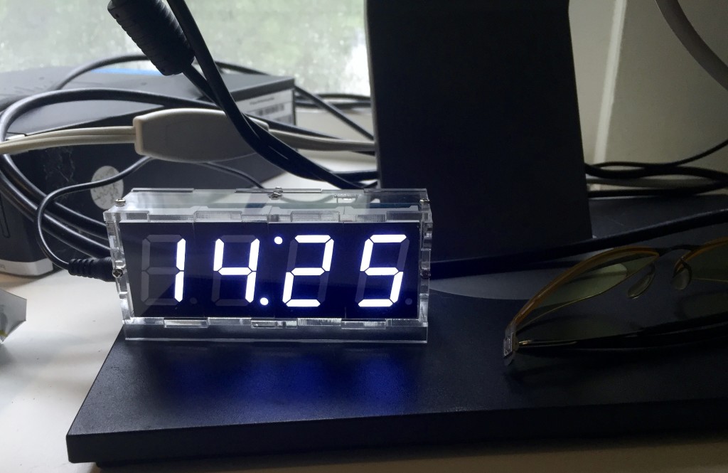
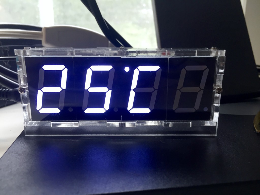
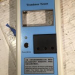
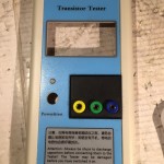
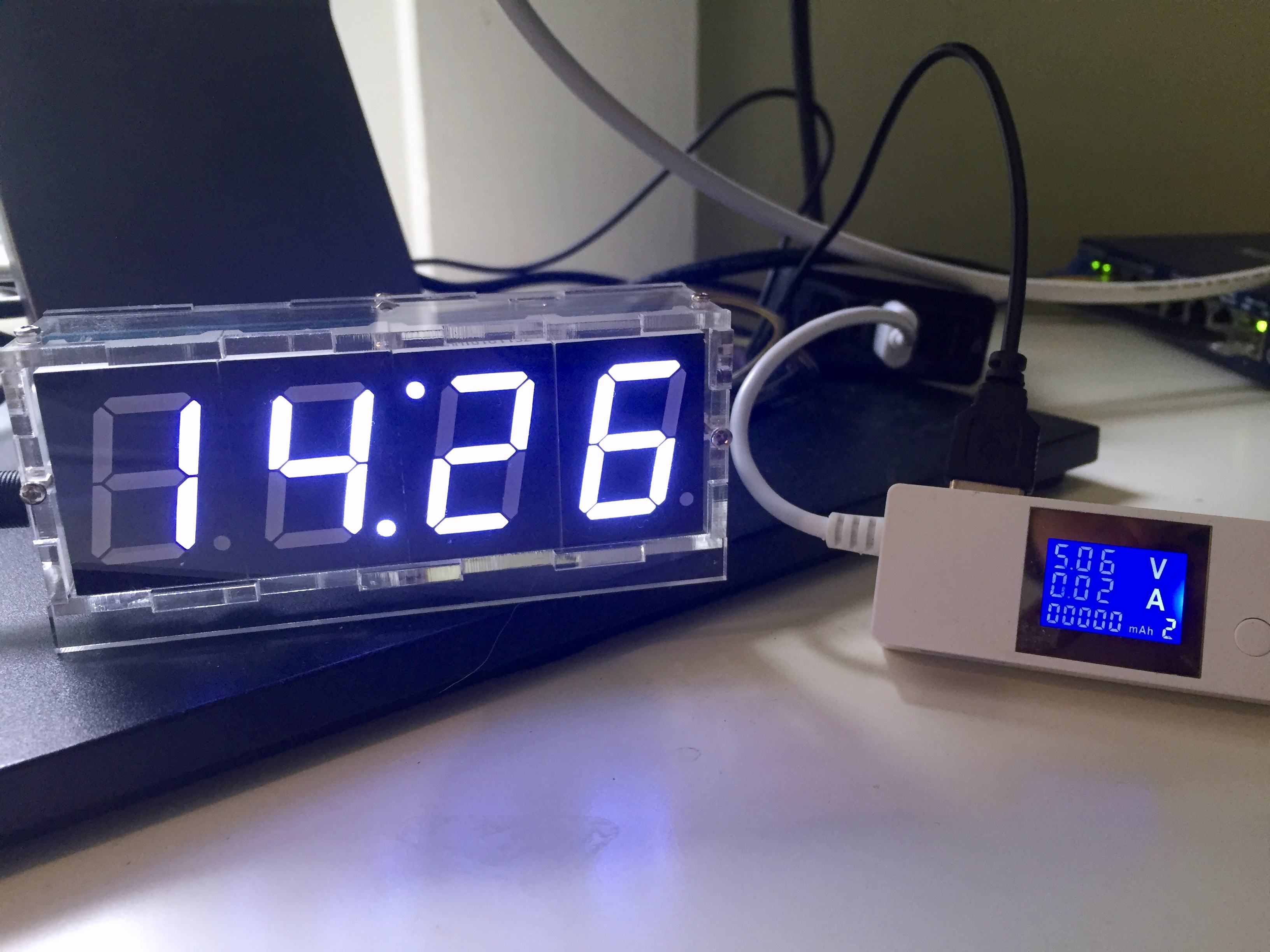
I’m still not sure why I was so attracted to the kit, even now that I have it assembled and working on my desk, but I have an idea. I think a big part of the appeal is the minimalism of the device. From the front, all you see is the inch high LED digits. The circuitry is all on a board hidden behind the LED modules. The optional clear acrylic case is similarly minimal. It’s just six pieces of clear acrylic, with tabs and notches cut to interlock, holes for the six screws and slots for the six nuts that fasten it all together.
Features:
- 1″ white digits (other colors available)
- Clock (24hr/military time only, so far as I can tell)
- Temperature, Centigrade only, alternates with time display
- Alarm
- 5v power with cord for powering from a USB connector
- Battery backup for the clock.
The kit comes with all the thru-hole parts needed to assemble the clock and 8.5×11″ sheet of paper with the instructions printed on one side. The instructions are probably enough to build and operate the clock given some basic familiarity with assembling electronics, which is not to say that they couldn’t be better.
Assembly
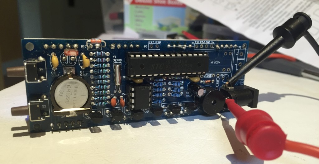
Assembling the kit is quite simple. There are about two dozen resistors of three different types to be added to the board, along with a with a diode. After placing and soldering these low-profile components, I added the six provided solid capacitors and the crystal, then the two IC sockets, six transistors, pezio buzzer, electrolytic capacitor, power socket, switches, and a surface mounted coin-cell holder.
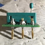
The transistors proved just slightly tricky, because the provided transistors are in a TO-92 package, while the PCB is layed out for something with a wider lead spacing like a TO-126. The solution is simple, bend the leads to fit, but it’s a bit fussy.
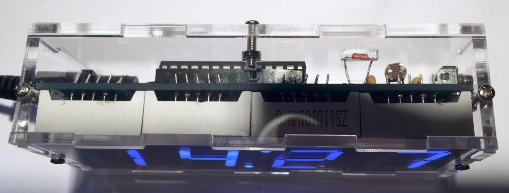
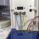
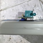
Before finishing soldering the components, I partially assembled the case so I could check the distance between the back of the board and the notch cut in the case to provide direct exposure to the thermistor. Photos of the assembled clock on Bangood show the thermistor sticking out high above the case, which strikes me as ridiculous and unnecessary. I decided that ~1cm off lead between the board and the component was enough to position it in the cutout while remaining protected by the case. I bent the leads to be parallel to each other and perpendicular to the axis of the thermistor package, then 1-2mm from that bend, I bent both leads at another right angle, so the leads remained parallel in the same plane, and the thermistor was a elevated slightly above it. I then soldered the thermistor to the board so there was about 7mm from the PCB. I did something similar for the photoresistor, so it could face upward. I bent the leads a couple mm away from the package, and then soldered the leads so they protruded about 5mm from the board.
-
-
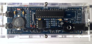
Once the components were all soldered, and the leads trimmed, I checked over the board and fixed a number of dodgy solder joints before adding the four 7-segment LED modules on the opposite side of the PCB.
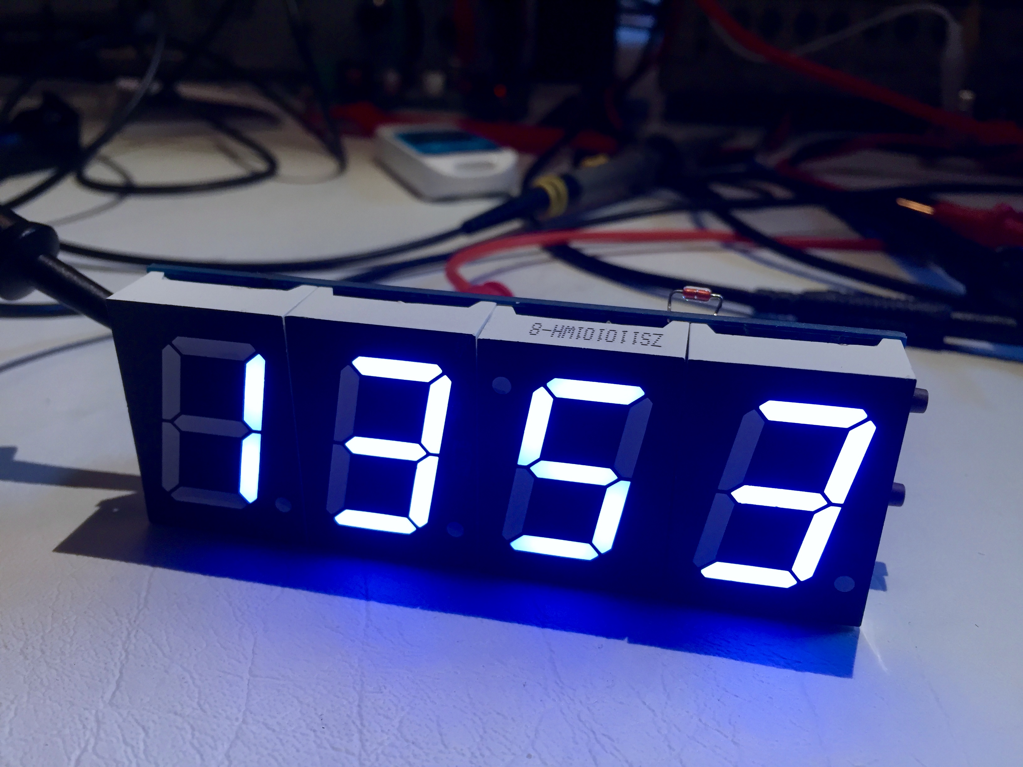
The third digit brought unexpected difficulty. It is supposed to be rotated, so that the dot that usually sits at the lower right to serve as a decimal point, will instead sit at the top left, to serve as the top dot of a colon separating hours from minutes formed with analogous dot at the bottom of the previous digit. This rotation presented a problem, because the leads at the top and bottom edge of the LED packages are offset, rather than centered, and the PCB wasn’t laid-out to account for this. All the leads had to be bent to accommodate. Again, a relatively simple task, but fussy in practice, because of the need to maintain the spacing between the 5 leads on each side so they will slip into the holes on the PCB.
Troubleshooting
At this point, I fit the ICs to their sockets, powered up the clock, and found that it worked. Or should I say, mostly worked? The left-most digit didn’t light up. I tried resetting the device as described in the instructions, but it still didn’t work. I checked all the solder joints for the LED module, and they seemed Ok, but I touched some of them up with another pass of the soldering iron. I also consulted the schematic to figure which transistor is responsible for strobing the power to the module and checked/touched-up its leads. The first digit still wasn’t lighting up. It was time for bed.
After a good nights sleep, and breakfast out with friends, I returned to troubleshooting the clock. I spent 15 minutes or so using the continuity function on one of my multimeters to trace out part of the circuit and better associate the schematic with the actual layout of the PCB. In particular, I was interested in the portion of the circuit responsible for powering the problem LED module. I figured out the center pin on either side of the module provided +5v, and that there seemed to be good continuity between that and the collector lead of the controlling transistor (Q1). I also found that there was proper continuity from the base of the transistor to the associated resistor, and that the other end of the resistor was, indeed, connected back to an output pin on the microcontroller. Finally, the emitter was properly connected to the 5v supply.
Since everything seemed to be connected properly, I needed to look elsewhere to figure out why the clock wasn’t functioning properly. I thought, perhaps, one of the components was defective. Rather than going to the trouble of testing them individually, either in or out of circuit, I decided to power up the device again, and use an oscilloscope to inspect the signals at various points in the circuit, and compare them against the signals at analogous points for the other functioning digits. This would help me pinpoint the component in need of attention.
That was the idea, anyway. Once I powered the clock up again, the problem digit lit up. I’m not sure what happened. Perhaps my probing and shifted a faulty solder joint back into contact? I tried pushing on a few spots, to see if I could reproduce the problem, but nothing happened. In the end, I decided I had better problems to solve than chasing down an intermittent fault in a $12 clock kit, mounted it in the case, and called the project done.
Other Details
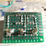
The PCB has some unpopulated areas. The documentation doesn’t say much about them, other than that they are “DIY” areas and no components should be installed. The schematic casts some light on what they are for. There are some headers for in-circuit-programming, and another which, I think, may be for resetting the MCU. There is also space for a relay, and an accompanying space for a connector/header for attaching the switched load. Given the design and clearances on the PCB, and the width of the associated traces, I’d guess that it is only suitable for switching low voltages at modest currents (~1A, tops). The firmware also seems to support this relay by allowing you to set an our to turn it on, and and hour to turn it off.
For what it is worth, the device uses a pre-programmed STC15F20EA_28 microcontroller in a DIP package. This MCU comes from STC Micro, in China. It has an implementation of the 80C51 CPU, along with 4K of flash, 256 bytes of SRAM, an 8-channel, 10-bit AD converter and 1K of EEPROM. This chip isn’t particularly hobbyist friendly, other than being inexpensive. Someone did create software for programming these chips called ‘stcdude.’ It is analogous to ‘avrdude’ used for programming Atmel avr microcontrollers. You’ll also need a compiler like SDCC (small device C compiler). That, and experience doing embedded development without much handholding. This isn’t an Arduino, nor is it Arduino compatible.
The MCU is complimented by a DS1302 clock chip (or something that functions like one), which stores the alarm settings, and keeps time on battery power when the external power isn’t connected.

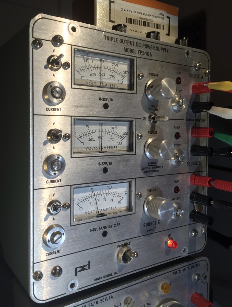
I measured the power consumption using a USB meter, and it read 0.01-0.02a, or 10-20mA. In theory, you could probably run it for ~4 days off of a modest single-cell USB powerbank. In practice though, it probably doesn’t draw enough current to keep most USB power banks switched on.
Conclusion
I’ll give this kit a solid B overall. The kit and instructions are a B- because of the layout problems I mentioned above. The finished product is a B to a B+. It think it is attractive, and useful, but as an American, the fact that it only displays time in 24-hour mode and temperature in Centigrade undermines its utility somewhat.
I should also say that while the temperature seems accurate to within a degree or so, I have no idea how well it will keep time.
