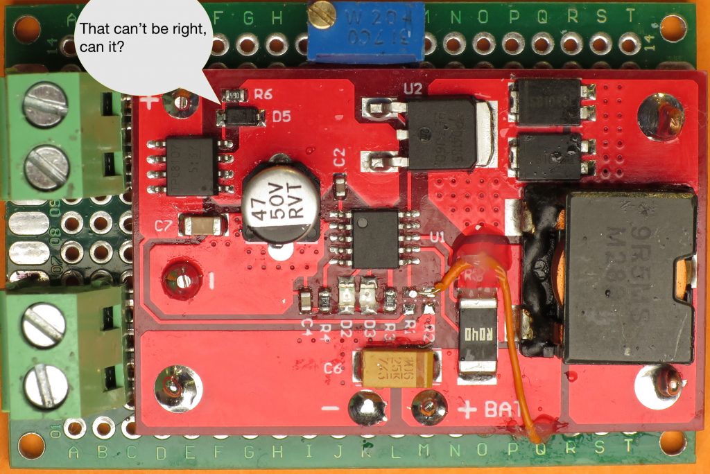
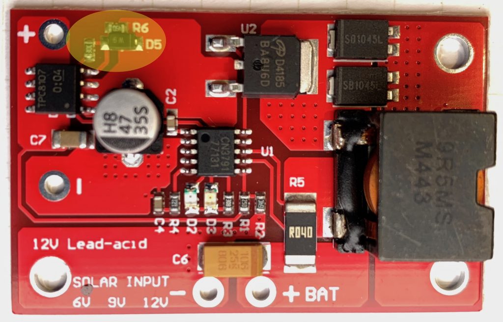
Last year, I paid about $3.66, with shipping, for this solar-powered MPPT lithium ion battery charging module on eBay to use with my small solar panels and scavenged 18650 batteries. It has some issues.
First off, the version I purchased/received is intended for 9v solar panels and I wanted to use it with a ~6v panel. This is set with a resistor divider. Careful study of photos from product listings showed that the divider was implemented using the same resistor value for the high segment of the divider, changing only the value of the lower segment’s resistor to change the setpoint.
The high segment had a value of 178KOhm and the low ranged from ~42KOhm for a 6v panel down to 12.6KOhm for an 18V panel. I didn’t have any SMD resistors of suitable value in my supplies, and I couldn’t find any I could scavenge on any surplus PCBs. I decided to use a trimpot instead. I had a variety on hand, and it would allow me to experiment on the optimal clamping voltage for the panel I had on hand, and an 18V panel I’d ordered. I chose a 200KOhm trim pot with the idea that approximating the total resistance of the existing divider would help preserve the stability of the control loop. If I were going to do it again, I’d probably choose a different configuration to minimize the impact of the pot’s temperature sensitivity. A simple choice would be ~20KOhm trimpot, configured as a variable resistor (short the wiper to one terminal) used it to replace the low segment, leaving the 178KOhm resistor in place.
After adding the potentiometer, I connected the battery and panel and adjusted the potentiometer until I maximized the charging current. I was a little surprised by how low the panel voltage was, and so I started poking around. The first thing I checked was the voltage drop across a P-Channel MOSFET on the panel input. I was surprised to find that it was 500mV, though knowing that, I wasn’t surprised the IC was noticeably warm. The panel was dissipating 1/10th of the panel voltage over the MOSFET!

Some of the photos on some of the product listings showed a simpler circuit, without anything in the panel input current path. My guess is that the MOSFET and accompanying resistor and diode were added in a revision in order to protect the circuit in case the panel polarity was accidentally reversed, and/or to block leakage of charge from battery through panel at night. A schottky diode would accomplish the same thing more simply, but with a voltage drop of ~300mV. Properly implemented, a MOSFET based “ideal diode” would have an effective resistance of ≥ 50mOhm, and a voltage drop of ≥ 50mV at the ~1A max current my panel could deliver.
I’m not completely sure how the circuit was intended to work, but clearly, it wasn’t doing the job. I wondered if it would work properly if I was using the module with a 9V manual, as intended, but that didn’t seem possible, either. The panel + was connected to the MOSFET’s source, the rest of the circuit to the drain, and the gate was connected to the drain via a resistor and diode. By my reasoning:
- that the gate would ≅the potential of the drain
- the voltage drop from source to drain should be as close to 0V as possible in order to maintain the efficiency of the curcuit
- therefore, Vgs would/should approximate 0V
- but it won’t because the Vgs threshold for the MOSFET was ~2V!
I wasn’t sure how to fix the circuit, but I was sure that the gate needed to be pulled down to a lower voltage, so I cut the trace connecting the resistor the drain and connected it to ground instead. It worked well enough that the voltage drop over the input MOSFET went from 0.5V to a trivial number. I’m pretty sure though that I didn’t fix the protection function.

I’ve since received another version of the module which has revised the input circuit. The diode and parallel resistor connecting the gate and drain are still used, but there as another resistor which connects to the charging indication pin on the CN3791, and in so doing. This pin is open drain. When the battery is charging, it is pulled low, lighting the charge indicator LED AND pulling the input MOSFET gate low. Vgs ≅ -Vpanel ≅ Vs ≅-6V, turning the MOSFET fully on.
Thinking through this further… if the battery is charged and the panel is illuminated the gate will approximate the potential of the input MOSFET drain and, since the only load on the panel is the quiescent current of the module, then Vsd ≅ 0V ≅ Vgs and so the MOSFET will be off, save any current through the body diode.
If the panel is dark and the battery is charged then Vd of the input MOSFET will, at most, be at battery voltage (Vbatt), Vs will be ~0v, Vg will ≅ Vd, Vgs ≅ Vd and the input MOSFET will be off.
If the panel is reversed Vs will be below GND and well below Vg ≅ Vd ≅ Vbatt so Vgs will be Vbatt + Vpanel, and the MOSFET will be off. Note: This means that reverse polarity with an ~18V nominal panel would exceed the Vgs maximum of 20V for the TPC8107 MOSFET used at the input.
If I get around to it I’ll draw a schematic and add it to this post.
I agree with your assessment of the MOSFET input circuit. I used a lot of the older solar charging circuit boards without the MOSFET and I always had to add in a Schottky diode to avoid problems. This new input circuit saves me time and a diode.
Thanks for sharing your assessment and experience.
Can you please do a schematic of this? My students would like to build “clones” of this for their solar project but we can not find the matching schematic.
I never got around to it, I’m afraid.
my understanding of it is that the mosfet is P-channel connected drain-source, so the mosfet unwillingly conducts in an *off* state.
upon completing the charge, it switches to on and then it conducts from source to drain, so the panels disconnect.
but this is wrong, if there is still light outside, the panels would overheat and the performance would be reduced if the charging cycle restarts… and in summer the panel would get really hot.
i think this works for overvoltage also, the schottky diode would break down i.e. after 30V and i’d turn on the gate closing the circuit.
i’d rather go with a diode on the panel and this version of the board https://ae01.alicdn.com/kf/HTB1fsSJSFXXXXXJXpXXq6xXFXXXX.jpg
Good afternoon, which diode should I use for the solar panel? Thanks!