I picked up a 21W, 3-panel Balight folding solar panel-based USB charger from Amazon for ~$36 a couple of weeks back. It uses high-efficiency SunPower Maxeon cells much like similar 20-21W panels from Aukey, Anker and dozens of obscure brands. All of them have the same basic construction. They are all made from nylon ballistic cloth. Each fold has a panel made from two SunPower cells encapsulated in a flexible waterpoof sheet. The panels provide power via two 5v USB ports, which presumably have some sort of voltage regulator.
I wanted to know more about how the chargers worked. In particular, I wanted to know if they were wired in series, or parallel because I wondered if it was worth trying to tap into the raw output, before the USB regulator to reduce power conversion and resistive losses for some applications.
I thought I’d be able to get the information I needed by finding someone documenting a teardown of their own panel on YouTube or a blog post. Despite the dozens of variants from dozens of brands and a handful of manufactures though, I didn’t find what I was looking for.
So, I decided to dig up a seam ripper and open my panel far enough to get a look at the wiring, and tap in to it upstream of the voltage regulator.
-
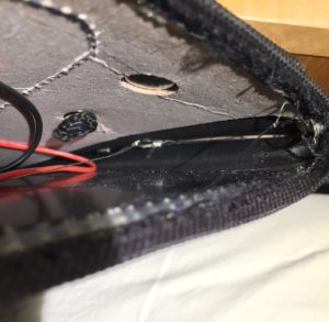
- Bad photo of wiring
-
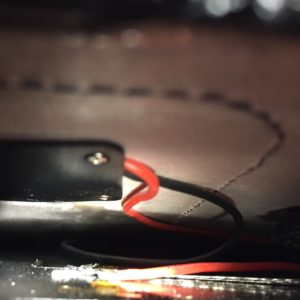
- Another bad photo of wiring
-
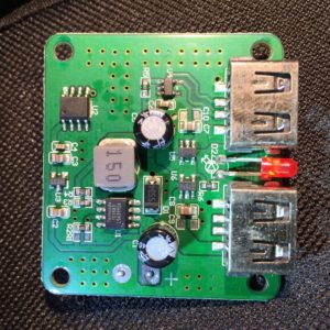
- USB Charger Output PCB
-
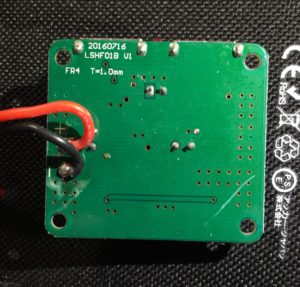
- Backside of PCB
The panels appear to be wired together with some sort of woven wire conductor. I had some hope that all the cells would be wired in series, to give a nominal panel voltage of 18v. Based on what I could see, and measuring the voltage before the regulator in full sun, it looks like each panel is wired in series, for 6v nominal voltage, and then the panels are wired together in parallel. I was disappointed at first, but this arrangement makes sense in upon further thought.
Using a 2s3p configuration means that the input voltage into the switching regulator should be pretty close to the 5v (actually, 5.2v with enough sun and a light enough load) output of the USB power regulator, which will typically have higher conversion efficiency than 12 or 18 volts. It also means that the manufacturers can stock one converter for everything from a 7W single-panel charger, up to a 28w 4 panel charger without the converter having to support a wide range of input voltages. Perhaps most importantly, it means that partial shading of one panel shouldn’t have a disproportionate impact on the power output of the entire array.
The only downside is that resistive losses in the cabling will be higher with lower voltage and higher current, but that the interconnects aren’t more than a foot or so, the resistive losses shouldn’t be too high.
As for the converter itself, I may look at it more closely and add some more details, but, a few initial observations:
- The PCB design has extensive ground planes on top and bottom, tied together with vias.
- Both outputs are served from a single buck-converter (step-down) power supply based on a Techcode TD1583, which is a 380 KHz fixed frequency monolithic step down switch mode regulator with a built in internal Power MOSFET.
- It looks like only port 1, at the top right in my photo, has the data lines connected, which suggests that it is the only one with fast-charge coding.
- IC U2 looks like it has its markings sanded off. I notice though that one of its pins is connected to the enable pin on the TD1583, leading me to think that it is responsible for cycling the output to make sure devices draw as much power as possible when the panel voltage rises again after clouds or an object reducing the light falling on the array pass. I don’t know if it is a MCU, some sort of timer, or comparator, or what, though.
There you go. I can’t be sure that other folding solar arrays like this one are wired in the same way, but if they only support a 5v output, I suspect they will be. I hope this proves useful to someone besides me.
Very interesting tear down. My guess is that each panel uses 12 cells in series. This gives a open clamp voltage of 7.2V and a maximum power voltage of 6V. The 3 panels are connected in parallel I guess resulting in the same voltage as input for the buck converter. Which makes sense because efficiency of the buck is way better from 6V to 5V than from 18V to 5V.
Do you know if it would be easy to connect the panels in series? Than you have a typical 12V panel (32..36 cells in series).
That sounds right. There appear to be two cells per panel, but each “cell” is actually cut into six strips, and all twelve strips must be connected in series. According to Sunpower’s specs, that’s Voc of ~8.2, and Vmpp of 6.9.
I think the panels would be quite easy to wire up in series, provided you have a good seam ripper.
It’s probably worth looking for some sort of flat conductors, so that they don’t put concentrated pressure on the panels when folded and packed up.
I’m probably going to put a tap in mine ahead of the buck converter so that it’s easy to bypass it and hook directly to an MPTT (lithium ion) charger when needed.
I’ve also put some thought into making them reconfigurable between series and parallel. If I go that far though, I think I’ll just get some bare, encapsulated panels as the starting point. It’ll help get rid of a bunch of bulk, too.
Only downside I can see with all these chargers wired this way is, what if you’re trying to charge in conditions that are not optimal? The voltage is close to the desired output and that’s great for efficiency when you have a lot of sun. What happens to the output with cloud shading or weak solar? Wouldn’t that pull the panel output voltage down too low (under 6 volts) for the regulator to work properly, possibly disconnecting the charge completely?
I was thinking of building one of these but based on 9 volt panel input instead.