I just received a USB / LiIon power module I paid ~$2, including shipping, for on AliExpress. The model is given as MH-CD32 (link goes to what I think is the original manufacturer, though I purchased it from another seller with cheaper shipping).
The board is supposed to be an all-in-one solution for powering a 5v (ie USB powered) device from a lithium ion battery pack. I suspect the IC was originally designed for use in a USB powerbank. The basic features are:
- Charging of 3.7v nominal, 4.2v max, lithium ion batteries.
- 5v charging input, 2.1A max charing current
- Battery protection for over current, over voltage and over temperature (for the charging IC, at least, there is no provision for a thermistor to sense pack temperature)
- 5v output, up to 2.1A
- 4-level battery “fuel gauge”
- Power path management: when the module is externally powered, it can power the load and charge the battery with any excess power from the supply.
- Control input that can switch the output on, or off, suitable for control by a microcontroller.
- 100uA quiescent current.
It accomplishes this all with a single 8-pin IC, a dozen discrete passives (an inductor, eight ceramic capacitors, three resistors), four LEDs and a microswitch. All in all, it looks like a useful module.
I’m curious about what IC it uses. The package has markings, but they aren’t useful; it’s marked MH CD42, which is the model number of the module. Nothing strange about that, except that Google searches don’t turn up anything, no Chinese datasheets, just more product listings for the module.
Ordinarily, the first couple of letters of a chip marking echo the name of the manufacturer, but in this case, they instead they echo the name of the module manufacturer “MH-ET.” It isn’t uncommon that manufacturers “sand” the IC package to obscure it’s origin. In this case though, it seems that MH-ET has either remarked the chips or, more likely, had the packages custom marked.
If I were a competitor, and this were a product that had some combination of a large market, a high margin and a high selling price, I could go to great lengths to discover the true origin of the integrated circuit. I’d start by gathering the basic details of the product and using that to infer the specs of the IC. There isn’t much guess work in this case, because the product is a manifestation of the the capabilities of the IC, and its typical for the sellers to use the ICs specs when describing the module, even when the implementation cuts corners that may compromise the specs.
I’d use the specs I gathered to search catalogs and databases for similar ICs and compile a list of candidates. If my goal is to produce a competitive product in terms of cost and capabilites, I’d investigate pricing of the candidates and if any of them met the functional and cost requirements, that might be the end of it.
If I couldn’t find an equivalent chip, or if I wanted to improve my negotiating postion, or if I was involved in making or selling a competing IC, I’d dig deeper. I’d look more closely at the details of the IC, the specific package, the functions of each pin, the details of the circuit connected to each pin and I’d compare them to the documentation available for candidates I’d previously identified based on basic specifications.
Beyond that, I could order samples of the candidates and test their behavior against that of that of samples of the unknown chip. Or, perhaps I’d use chemical or mechanical means to extract the silicon ship from the enclosing package and then examine it under a microscope before and after stripping away layers of metalization on the IC. This might show me markings like a date code, part number, or logo. It would certainly show me the gross and fine structure of the circult. All of them would help me find the true origin of the integrated circuit.
I’m not going to do that though, in fact, I’ve already spent more time writing about it than I’d like to spend on what I am going to do.
Rather than going to those lengths, I’m going to take a shortcut that I happen to have available to me: I remember seeing a similar module on eBay a few months ago and I remember that the IC on that module had a distinct an unfamiliar manufactuer logo on it.
It took a little longer than I expected, but I found the ebay listing, or one like it. There IC lacks a distinctinve logo, but it does have a clear part number “IP5306,” and that part number leads to a catalog listing on a distributor’s site, a datasheet and the manufactuer, a company called Injoinic Technology.
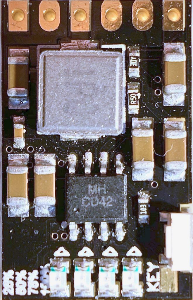
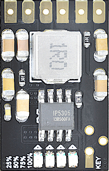
The PCB layouts are very similar. The IC pinouts seem identical. I tried tracing out the circuit, but I could only get so far without removing components. The only real question are pins 6 & 7.
My 4.5 digit multimeter shows ~0Ohms resistance between them, suggesting they are on the same node of the circuit. However, if the IC on my MH CD42 board is the same or equivalent to the one on the IP5306, then those pins should actually be on two separate nodes of the circuit. Pin 7, on the left, should be connected directly to the near side of the inductor, while pin 6 should be connected to the far side of the inductor, by way of the low-value 500mOhm resistor you can see in the photograph.
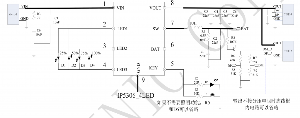
It wouldn’t be hard to pull off some components and replace them later, or it shouldn’t be, but I always seem to hit a snag on the easy jobs, like loosing a tiny component, or delaminating part of a trace. Fortunately, I have a nice Keithley 2000 6.5 Digit DMM. It’s serious overkill for most stuff, and measuring miliohms isn’t its forte, but it only took 30s to boot up (it actually has a Motorola 68030 process, like an old Mac ][, or SE/30 computer), and less time than that to show that the path from Pin 6 to Vbatt had 500mOhm higher resistance than the path from Pin 7.
So, my conclusion is that the MH CD42 IC is actually an Injoinic Technology IP5306. It’s possible that it is a “clone,” or that they both actually come from a third party, or are otherwise derived from the masks and foundry. It may also be true that there is another IC on the market that defined the specs and pinout and that a very narrow market niche has emerged around it. I already know more than I need to know, and if you’ve read this far, then you know it, too.
Pingback: What IC does the MH KC24 USB QC2/3 Buck Module Use? | Tech Obsessed
Hey eas!
I didn’t find any contact information, so I hope I can get an answer from you here.
Is there any chance that have you tried the MH CD42 (or the other one) with a raspberry pi? I’m looking for a cheap UPS solution which doesn’t reboots the pi when switching to battery mode. I know that the IP5306 is capable doing that, but I’m not sure about MH-CD42 has the right implementation of it.
Thank you for your answer!
Adam
I don’t know, sorry. I’ve donated most of my electronic parts; I was accumulating them faster than I was using them.
I have tried IP5306 module with NanoPi NEO. The result is similar to all other tests of the similar devices: when the external power is turned off, there is a short-term loss of the output voltage and NanoPi simply freezes.
I’m not surprised that your multimeter reads a ~0ohms between pins 6 and 7, as the inductor presents a low resistance path between the two.
This was helpful! I had the same question!
Did you ever find a datasheet in english?
Nope, never did, unfortunately. It probably doesn’t exist.
I ran the Chinese datasheet through Google Translate, and it pretty much mirrors the specs for the powerbank shown at the top of the article.
Thanks for the extremely helpful post!
I’m looking for the manufacturer of the board, to see if I can get a version with some minor modifications (either with a castellated header, or maybe with micro-USB input and some JST XH connectors for the connections).
FYI:
The Injoinic web site has the english datasheet PDF:
http://www.injoinic.com/wwwroot/uploads/files/20200221/0405f23c247a34d3990ae100c8b20a27.pdf
It’s part of their Powerbank SoC product line: http://www.injoinic.com/product_detail/id/21.html%20target=
It looks like the design and tolerances on the MH-CD42 board are much worse than on the IP5306 board. Look at the number/size of vias, and the pad sizes for the LEDs. The MH-CD42 LEDs end up sliding around on the oversized pads, and looking pretty lousy because they’re not evenly aligned. Both have ridiculously small through holes for connections.
Fully-Integrated Power Bank System-On-Chip with
2.1A charger, 2.4A discharger
http://www.injoinic.com/wwwroot/uploads/files/20200221/0405f23c247a34d3990ae100c8b20a27.pdf
Nice article, thanks for this. I’ve spent nearly 4 hours today Researching Lipo charge / use circuits and have come to the conclusion that it’s just too annoying!
I’ll stick to an external USB power bank for my widget for now
Great Article! Thanks for your investigations!
This module sells for astonishing 60 €ct shipped at 100 pieces from Aliexpress.
https://de.aliexpress.com/item/32999118705.html?spm=a2g0o.productlist.0.0.756741122cp0Az&algo_pvid=016a5557-6469-4449-ab35-47e6af6c541b&algo_exp_id=016a5557-6469-4449-ab35-47e6af6c541b-16
Thank you so much for sharing your findings!
Very much appreciated.
The difference between 0 ohms and 0.5 ohms is not very much when you also have the test leads in the picture, and if it’s a cheap meter. I’m not surprised the multi meter is reading them as a dead short. But also, it’s probably an “optional” resistor for the Battery voltage sense pin. So if the resistor is not there, the inductor creates a dead short as mentioned by another commenter. If there’s no resistor, it just cant detect overcurrent I’m guessing.
Nice Article.
I’ve been working with this board for a little while trying to replicate the functionality of the Adafruit PowerBoost boards. At the current prices difference… I think it is worth the effort. Often the PowerBoost boards cost more than the project itself, so a cheap alternative is really needed.
Great review,
I wonder one thing; recently i bought a module on Aliexpress, 5V/2A charge disharge module with USB type-C input, came with an ic marked as ETA9741. Module works hilariously even when switching to battery mode no shortage occurs(for those looking for ups).The thing making me think though, both the input and the boost output connects to same line. When module is idle, and not charging, it is outputting 4.80V to the type-C port as well as to the USB output. With attachment of load greater than 50ma module detects load and boosts 5V. To start charging process output & input needs to be interrupted with a voltage greater than 5V via an usb adapter.
The thing boggling my mind is how come it detect charger and i wonder if it can hurt sensitive electronics like USB output of PC or mobile phone etc. as it behaves like a power source rather than a load.
Links: ETA9741datasheet
(https://datasheetspdf.com/pdf/1424982/ETA/ETA9741/1)
Module (https://www.aliexpress.com/item/1005003776830859.html?pdp_npi=2%40dis%21USD%21US%20%240.52%21US%20%240.50%21%21%21%21%21%40211b5e2616557124598876817e34d6%2112000027128885074%21im)
I can confirm that the 0.5 Ω resistor is for battery voltage sensing. I spent half a day fiddling with resistors to figure out if this piece of crap can be made to remain on with a load of 70 mA. I failed. A similar chip, PB0059E-HOTCHIP, wants 60 mA.
The three modules I tested won’t stay on continuously until the load is >200 mA!
For anything “low powered”, modules with the “MH-CD42” are useless. At least not until the module is used to power a microcontroller that can pull pin 5 to ground every 20 s …
Have you found any solution that allows the application on ultra low power devices?
I intended to use these modules in a controller, then I realized that it turns off after 30s due to the low power consumption it presents
Hotchip PB0059E is the chip on mine.
The 0.5Ohm resistor is simply a low pass filter for the battery voltage measurement. 0.5ohm x 22uF gives a time constant of 11usec. This just evens out switching noise of 500kHz. I would think the circuit probably also works without it if the battery is not too far and the filter cap has a low esr (low inductance). I operate an ip5305 without such a filter and it just works fine, but the 22u cap is a low esr type and traces thick and close to the ic, and so is the battery.
It has nothing to do with charge current etc.
That’s interesting, and it makes sense. Do you know how to adjust the minimum current before the chip switches off battery power? It must sense the current somehow…
I’ve discovered that it’s more likely the cheaper variant of the same chip: FM5324GA
Same story as always) Many manufacturers offer the same pin compatible and same function chip for cheaper than the original
At least they changed the name a bit..
Hello there,
I have designed a handheld device, and when I went from development to prototype I couldn’t find the mhcd42 so I had to replace it with the IP5306.
(My device is composed of an ESP32, an RFID PN5180 sensor and the IP5306 charger/booster. Wiring was according to the schematic on IP5306 datasheet V1.31.
My issue has to do with the battery sensing. LED 4 (100% full) remains blinking forever, as if it did not detect that the battery is already fully charged.
In version V1.31 of the datasheet, pin 6 (BAT) is wired to the battery through the resistor R4. However, in version V1.01, pin 6 (BAT) is directly wired to the battery.
I wonder if I should be guided by the previous version?
Thanks in advance for your help,
Osmany
Hi OSmany. Did you find a solution?
Der “IP5306” sowie der Clon “FM5324” ( beide 1:1-Pin-Compatible!); haben großes Problem: Der USab-5V- Out sind nicht COMPLEAT ABGESCHALTET! Die im Datasheed erwähnte angebliche Standby-Function existiert garnicht! Der Pin 8 Out ist IMMER ACTIV!! NUR die LEDs werden abgeschaltet!! AmvPin 8 liegen DAUERHAFT – OHNE Last – weiterhin immer 3,3 V an!!! Heisst: Der Chip schaltet das Booster NIE in den Standby!!! Das ist im Datenblatt NICHT erwähnt!! Der Booster geht nur auf ca. 3,V3 zurück, wenn am Pin 8 Out KEINE LAST bzw. kleiner als ca.50mA erkannt wird!! Das Problem: Der Chip ist GEFÄHRLICH für Mobilphones und andere 5 V Geräte!!!! Weil DAUERSPANNUNG IMMER ANLIEGT UND NIE ABSCHALTET!!! Das Datenblatt zu beiden Chip-Versionen LÜGT!!! Problem Nr 2: Weil Problem NR 1(!!):
Angeschlossene Akkus an Pin 6 werden dadurch ENTLADEN!!! WEIL BOOSTER IMMER ACTIV ist!!! NO STANDBY!! NO POWER OUT OFF!!! IT’s A NEGATIV PROBLEMS!!! THIS CHIPS ARE ALSO NOT FOR MOBILE POWER(-BANKS)!!!! THIS CHIIPS DICHARGE THE ACCU-PACKS!!! WITH OR NOT OUTPUT 5V LOAD!!!! THIS ICs CANNOT AUTO POWER OFF BOOST AND NOT STANDBY!!! THE POWER OUT IS GENERALY POWER ON!!!!! SO, RHIS CHIPS ARE ONLY FAKES!!! TECHNICAL COMPLETLY NOT WORKING, SO IS DOCUMENTARY IN THE DATASHEEDS!!!! THIS FUNCTIONS STANDBY AND OR POWER OFF ON POWER OUT PIN 8 ARE NOT PRESENT!!!
My Name, Email and or other privacy Data are ALL NOT for Internet!!! This all are ONLY MY PRIVACY DATA!!! HERE, I HAVE FREE RANDOMED GENERATED DATA IN THIS DOCUMENT!!! ITS FOR MY PRIVACY SECEURITY!!!! You underständ?
Der “IP5306” sowie der Clon “FM5324” ( beide 1:1-Pin-Compatible!); haben ein großes Problem: Der USB -5V- Out ist NIE COMPLETT ABGESCHALTET! Die im Datasheed erwähnte angebliche Standby-Function existiert garnicht! Der Pin 8 Out 5 V ist IMMER ACTIV!! NUR die LEDs werden abgeschaltet!! Am Pin 8 liegen DAUERHAFT –AUCH OHNE Last – weiterhin IMMER MINDESTENS 3,3 V an!!! Heisst: Der Chip schaltet das Booster NIE in den Standby!!! Das ist im Datenblatt NICHT erwähnt!! Der Booster geht nur auf ca. 3,V3 zurück, wenn am Pin 8 Out KEINE LAST bzw. kleiner als ca.50mA erkannt wird!! Das Problem: Der Chip ist GEFÄHRLICH für Mobilphones und andere 5 V Geräte!!!! Weil DAUERSPANNUNG IMMER ANLIEGT UND NIE ABSCHALTET!!! DAS FÜHRT UNWEIGERLICH, AUCH BEI VORRÜBERGEHENDER NICHTBENUTZUNG DES BOOSTER-ICs, DENNOCH ZU MAXIMALER ENTLADUNG DER ACCU-PACKS!!! HIER MUSS DANN AUCH DAS ACCUPACK ÜBER EXTRA-POWER SCHALTER AUS-GESCHALTET WERDEN!! SONST, WONST WERDEN DIE ACCUS ENTLADEN, DA DAS BOOSTER IMMER ACTIV IST!! KEIN STANDBY!! KEIN POWER OUT OFF!!! Die Datasheeds zu beiden Chip-Versionen LÜGEN hier nämlich!!! Problem Nr 2: Weil Problem NR 1(!!):
Angeschlossene Akkus an Pin 6 werden dadurch ENTLADEN!!! WEIL BOOSTER IMMER ACTIV ist!!! NO STANDBY!! NO POWER OUT OFF!!! IT’s A NEGATIV PROBLEM!!! THIS CHIPS ARE ALSO NOT FOR MOBILE POWER(-BANKS)!!!! THIS CHIIPS DI-CHARGE THE ACCU-PACKS!!! WITH OR NOT OUTPUT 5V LOAD!!!! THIS ICs CANNOT AUTO POWER OFF BOOST AND NOT STANDBY!!! THE POWER OUT IS GENERALY POWER ON!!!!! SO, THIS CHIPS ARE ONLY FAKES!!! TECHNICAL COMPLETLY NOT WORKING, SO IS DOCUMENTARY IN THE DATASHEEDS!!!! THIS FUNCTIONS STANDBY AND OR POWER OFF ON POWER OUT PIN 8 ARE NOT PRESENT!!!
And for the Website-Admin this Info:
My Name, Email and or other privacy Data are ALL NOT for Internet!!! This all are ONLY MY PRIVACY DATA!!! HERE, I HAVE FREE RANDOMED GENERATED DATA IN THIS DOCUMENT!!! ITs FOR MY PRIVACY SECEURITY!!!! You underständ?