An update on the Power Designs TP340A bench power supply I’ve been restoring and repairing. I started by replacing a bad Sprague electrolytic capacitor. While I was at it, I decided to replace all the big electrolytic caps. That didn’t go so well, because I put two of them in backwards and caused them to vent. After replacing the vented caps, I noticed that the supply wasn’t behaving quite right, and found that some key voltages were out of spec. After some trial and error, I figured out which components to replace to get everything in spec.
I was pretty pleased with myself, but the next morning I realized that I’d been too hasty to write off some drift I encountered while calibrating Source B. I started load testing Source A & B, both separately, and in tracking mode while watching the output on a multimeter, and my oscilloscope in roll-mode:
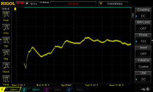
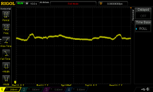
It didn’t take long before the voltage of the output on Soure B started a random drunken walk over the range of a 0.5v or more. After a while, it stabilized again and I left it to run a few hours without incident.
Before turning things off, I started fiddling around, connecting and disconnecting things, varying the current and voltage, trying to provoke another excursion and before long, it did it again. I really wasn’t sure what was going on, and figured I’d need to consult the schematics and start a long process of trying to figure things out.
Lucky for me, over on the Eevblog forum, user nanofrog, who’d helped me pick out replacement capacitors, checked in on my progress and I shared what I just described above. He replied suggesting I look for thermal-related issues, like a bad solder joint. That made sense! I didn’t have any obvious problems when the unit was running, just when it was heating up and cooling down.
I spent a good chunk of my 4th of July indoors, in a warm, dimly lit room, abusing the PCB of my power supply with alternating blasts of hot air from a hair dryer and cold spray from an inverted can of electronics duster while measuring things with my scope and DMM. I also loosened mounting screws so I could flex the PCB. I wasn’t getting the dramatic results I was hoping for, but eventually, with enough persistence, I was able to get bad behavior by focusing my attention on the lower part of the board near C211. From the schematics, I could see that C111 had a role in damping feedback going to the main voltage regulating op-amp. I inspected the PCB closely looking for a bad solder join on this capacitor, or any of the components in circuit with it.
After a good hour spent squinting and angling to get a better look I hadn’t found an obvious problem, but I saw a few solder joints that I was suspicious of. So, I heated up my soldering iron, daubed on some RMA flux and made sure I had some leaded solder handy and got to work touching-up the questionable joints.
Then I started testing it again. I repeated the cycle of heating and cooling multiple times without obvious problems. This morning I got up and did it some more, then left it running for a couple hours before calibrating it again.
This time, I didn’t run into any drift during calibration, but having declared victory prematurely once before, I wasn’t ready to call the project done. I needed more convincing.
Earlier in the troubleshooting process, I had noticed some subtler behavior when the PSU thermal equilibrium. All though Souce B’s voltage was stable from second to second and minute to minute under a steady current, it had poor load regulation, with changes of ~30mv or more when between 0 & 1A of current. Moverover, if I used the statistics function on my Keithley 2700 multimeter to take 1000 readings of the voltage while the unit was under a constant load, I found that the Standard Deviation in reads was 10x higher for Source B compared to Source A.
First, I checked load regulation of both Source A & B between 0 and 1A at ~10V. Both had a total swing of ~3-4mv. According to specs, it should be ~2mV. My measured values are worse, but not dramatically so, and also pretty similar between channels, suggesting to me that I’d managed to fix the major instability issue.
Next thing I did was take 1024 readings for each source with a constant load of ~1A, again at 10V. Both channels had a standard deviation of ~25-30uV, whereas previously, channel B would have been 10x. More evidence that I’ve indeed solved the major instability problem.
I haven’t checked transient response or ripple, or thermal stability or long-term stability, but for the things I have checked, this PSU is very close to its original specs. Its also good enough for my purposes right now, so I’m going to call this project done and move on.
I have a TP340 which really should have it’s capacitors changed even though it seems to be working pretty well.
You mentioned that you got some help from nanofrog about suggested replacements. I wonder if you would be willing to share the info. Finding proper replacements for these old caps in PD supplies is a real problem since they selected their specs as part of the design. Some times just a cap with the same basic specs may not be enough.
BTW, great blog. Love the EDC 521 and thanks for the interior photos. Wish I could get one but I really can’t afford one; they seem to be quite expensive right now. I have a vs330 which appears to work pretty well but needs some cleaning.
Anyway I’d appreciate any info on replacement caps you’d be willing to share.
Thanks,
Bob England
Thanks for the comment, not sure why I didn’t notice it until now. Good to hear that someone is getting value from some of my posts.
I used these vishay caps to replace the Spragues. I don’t remember the exact selection criteria, other than going for some with a high operating temp since the originals hadn’t held up.
They are the only electrolytic that I replaced that are connected to regulated power rails (for the bias supply). All the others are just filter caps on the unregulated rectified DC. There are filter caps on the output, but I haven’t replaced those.
The EDC 521 is nice, but rather huge. I’m lucky to have gotten a good price on it. When I sell it, it will probably help pay for some of my more foolish used equipment purchases.
Interesting articles on fixing your TP343B with good photos and a great outcome. Well done!
I bought one off eBay last night for a good price (the seller accepted my offer), though shipping was about twice the cost of the item due to it’s hefty weight. Mine looks to be in pretty good visual condition, which is good because I love the look of this design. I’ve needed a PSU for a long time and was considering getting a lightweight Chinesium unit from Amazon, but after browsing eBay for a couple of days this beautiful retro metallic look won me over!
I don’t suppose it will be working properly, if at all, when it arrives, so I’m hoping your blog should help me get it going again. These things have a habit of failing at similar points. Getting rid of those old caps will be a definite replacement… I expect they’re all quite dry inside.
Several years ago I bought a dirt cheap 90’s LG oscilloscope on eBay and got it working (or at least I got the CRT drive circuit working & stable again, but still need to fix the channel B input). I didn’t have a manual for that, so had to rely on probing around the board with a multimeter, crudely comparing the resistances across duplicate components to find the bad ones.
…So, this eBay “Sold As-Is” Special won’t be my first rodeo … and I have an advantage over last time by already having a manual for it! (albeit a poorish resolution PDF copy.)
Good luck with your new purchase!