I’m trying to build a triple emitter flashlight, but not just any triple emitter flashlight. I am not taking the path of least resistance, which has presented some challenges. But first, these are some of the salient details of what I’m trying to build:
- SST-40 Emitters
- Same 5050 footprint as the common XM-L & XM-L2 emitters.
- Better beam, less tint shift than an XM-L2 when used with a reflector,
- More efficient than an XM-L, XM-L2 or XP-L.
- Lower forward voltage than XM-L, XM-L2 and XP-L
- Only available in cold-white (6500K or 7000K), but the tint is pretty neutral
- Taken together, these characteristics make for an emitter than can be pushed to almost 2300lm @ 7.5A/27W off a single Lithium ion battery.
- Triple reflector: The simple path to a triple-emitter build is to use a triple-optic, but the available options don’t really give the spot+spill beam pattern I’m after.
- 26650 battery: Sofirn sells a great reflector-based triple emitter C8F host for just ~$14, MCPCB included. I have one. There are two problems with it. First, the provided MCPCB is for 3535 form-factor emitters. Second, it can drain any cell in no time, but 18650s have ~2/3rds the capacity of a 26650.
I have a reflector, and a host I can fit it to without much trouble. What I don’t have, and haven’t been able to find, is an MCPCB I can mount 5050 emitters to in such a way that they’ll line up with the reflector. I think the Noctigon XP32 has the right spacing for the reflector, but it only takes 3535 emitters. I thought I might have found a 32mm MaxToch PCB that would work, but it doesn’t.
My fallback plan is to solder some 11mm Sinkpad MCPCBs to a copper disc. The difficulty is getting them positioned properly and then keeping them in position while soldering them down. I’ve explored various ideas as to how to manage this feat, and I tried one yesterday.
I started by making a template in inkscape. It was a little tedious. Inkscape isn’t really made for technical drawings, so I had to double check dimensions and adjust alignment and sizes repeatedly. Once I had something I thought would work, I printed it onto some index card stock. Next, I smeared some non-corrosive silicone adhesive on the template, and positioned the little MCPCBs face down on the template. I pushed them down firmly, scraped away the glue around them with a toothpick so I could get a better view of the template, and then adjusted them until they were aligned as best I could.
A few hours later, after the glue had set, I double-checked the alignment, then I cut most of the paper away, to clear the way for my soldering iron.
I prepped the copper disc and the exposed metal bottoms of the MCPCBs by tinning them. I used lead free solder because I wanted something with a higher melting point than the eutectic sn63pb37 solder paste I use to reflow the emitters on to the MCPCB. I had trouble getting a nice even, thin, layer on the copper disc, so I filed and sanded the solder surface down before continuing.
I put a thin coat of rosin flux on the tinned surfaces of the copper disc and MCPCBs, and centered the MCPCB cluster on the disc. Then I heated the disc with my soldering iron. Once it was hot enough to melt solder, I fed solder wire to each MCPCB while keeping the copper disc hot with my soldering iron. Once they were all nicely flooded with solder, I tweaked the alignment with the center of the disc. Removed the heat, and pressed down evenly with a block of wood to get a nice close fit between the copper surfaces. Once it cooled down, I removed the block.
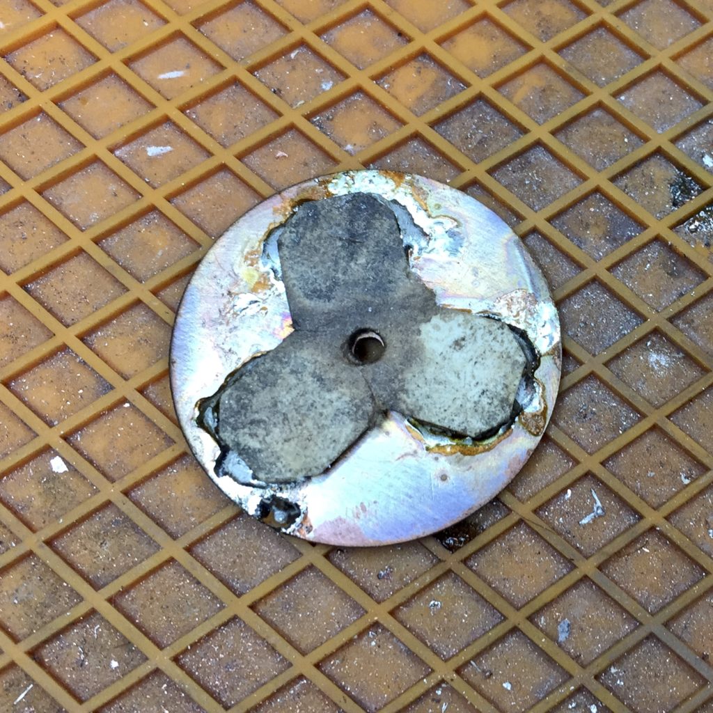
The first time I tried, the alignment of the MCPCBs was off center a bit, so I heated things up and tried again. This time the results were a little better. As you can see, the paper charred a bit, but I think it still did its job of keeping the three MCPCBs positioned relative to each other during the process of soldering them to the copper disc.
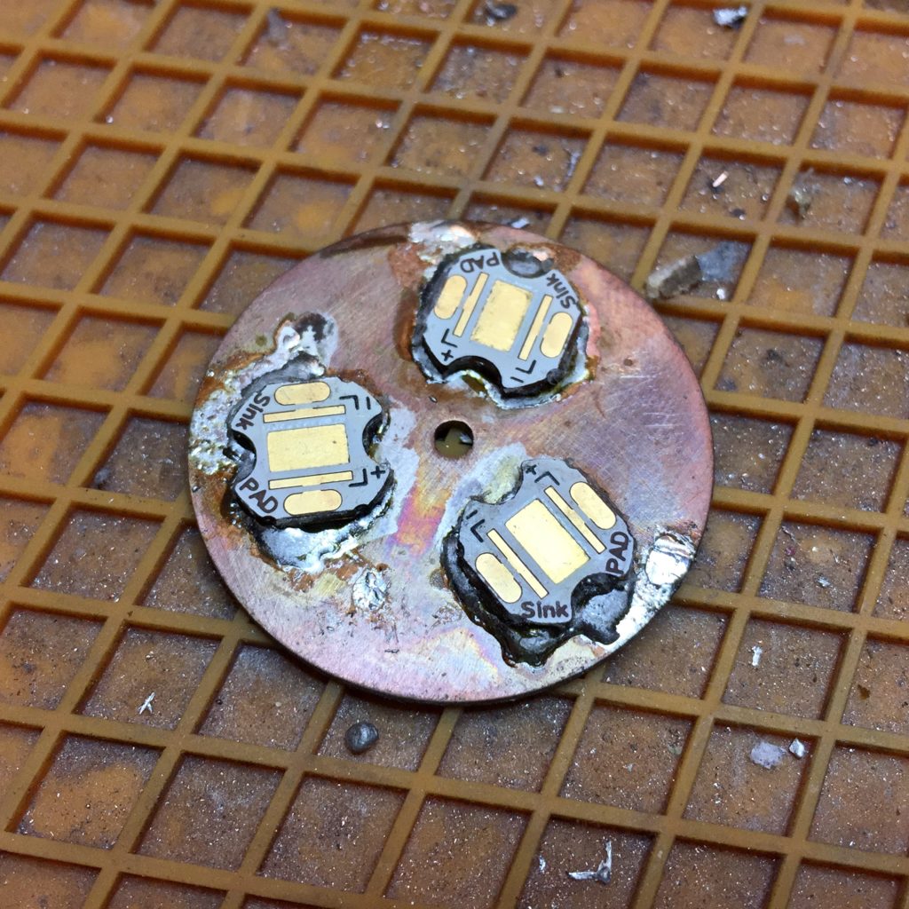
I peeled the paper and silicone adhesive off with tweezers, and then rubbed the remaining adhesive off with a cloth. This is the result. I’m pretty happy with it. Or I would be, if, after all that, everything was aligned properly with the reflector. It’s not.
I’m not sure what, exactly, went wrong. I think I had the spacing right on the template. I think the main source of error was probably in getting the MCPCBs aligned to the template while glueing them down to it.
I think that I’m just going to try reheating the assembly again and adjusting things until they line up better. If that works well enough, I’m just going to call it good and finish building the light.
If I can’t rework it well enough, I’ll probably desolder everything, clean it up, and use some thermal epoxy. It won’t be as good as the solder, probably, but it should be a very thin layer, so hopefully the thermal transfer will still be pretty good.
Update:
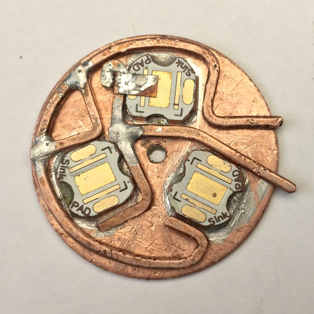
I reheated the assembly and adjusted the position of each MCPCB. I checked their positioning using the reflector before moving on to the next one, then one last time before removing the heat and letting the solder cool. It’s pretty good, but most importantly, it’s good enough. Now I have to figure out how to do the electrical hookups.
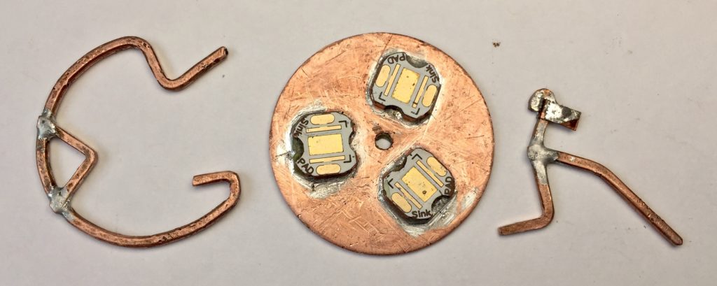
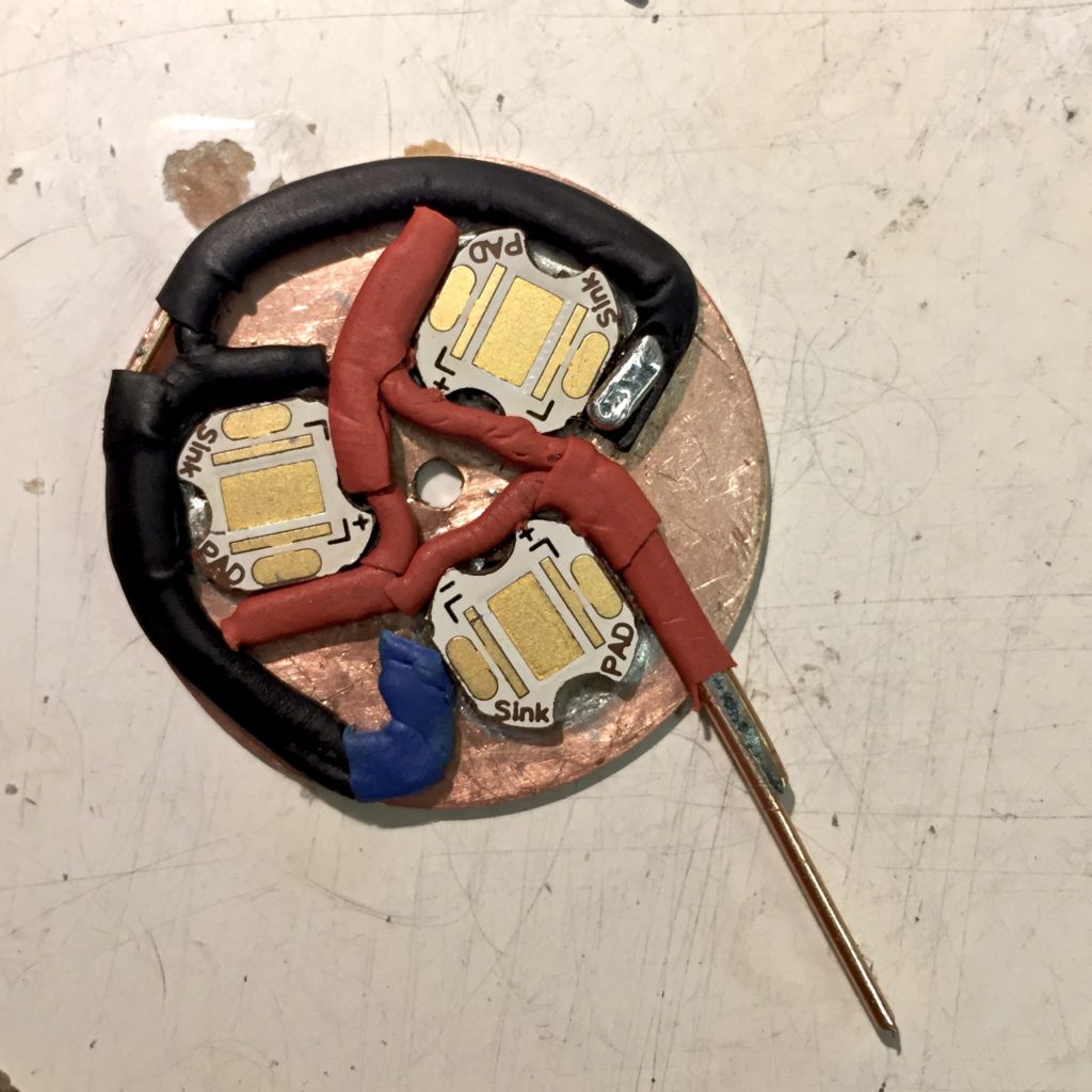 This is the first one I finished. I wasn’t happy with it for some reason, I think because I thought the insulated conductors were too thick, above the tops of the MCPCBs. I should have just stripped the heat shrink insulation and relied on epoxy or something, but I didn’t