My Keithley 2000 DMM craps out during serial communications with a PC over RS-232. When it does, the voltages on the TxD (yellow trace) and RxD (blue trace) lines look like this:
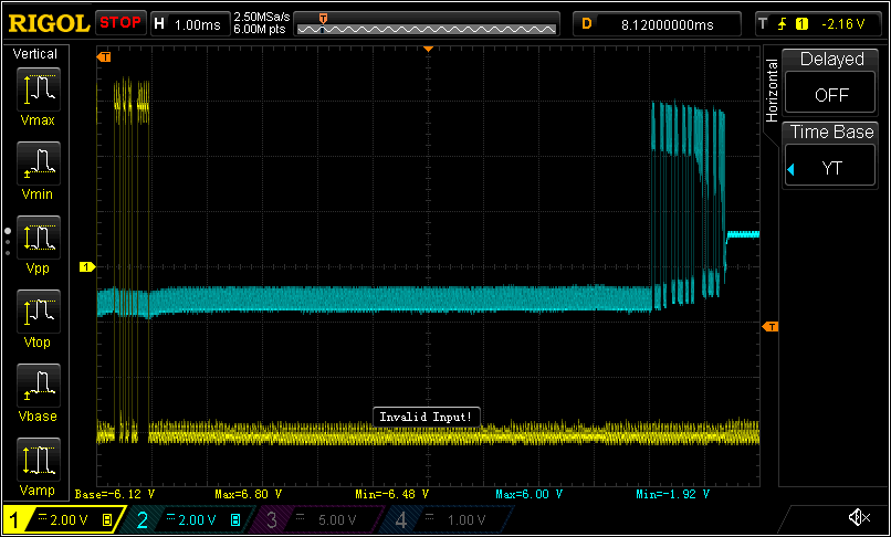
There are a few things wrong here.
- The idle voltage of the RxD line should be -7v or so, similar to that of the TxD line, rather than the -1.7v it starts at.
- The obvious decline in signal quality before the RxD locks at the ~1.2v shown at the end of the trace.
- RxS locks at 1.2v, rather than returning to it’s idle voltage.
I came across someone who had trouble with the RS-232 level shifter IC on the similar Keithley 2015, so I carefully checked it out. It seems to be well under-spec on the output of its internal -10v power supply, which can only deliver a sustained 6mA. The +10v supply, on the other hand, can provide much more. I also diligently checking of voltages and current delivery of all the signal lines both the multimeter and the USB to RS-232 adapter its connected to.
It appears that the PC is trying to drive the RTS line to +7v. At the same time, the multimeter is trying to drive the RTS line down to -9v, and its loosing. As a result, it can’t drive the RxD line below -1.7v, and eventually, while transmitting, it gets stuck at +1.2v.
But why is the the DMM trying to do anything on the RTS line? That’s the job of the “data terminal equipment,” or DTE. I checked the reverse-engineered Keithley 2000 schematic, and it shows that the RTS line is connected to one of the transmit outputs of the level-shifter IC, something I confirmed by doing a continuity test. This makes no sense to me.
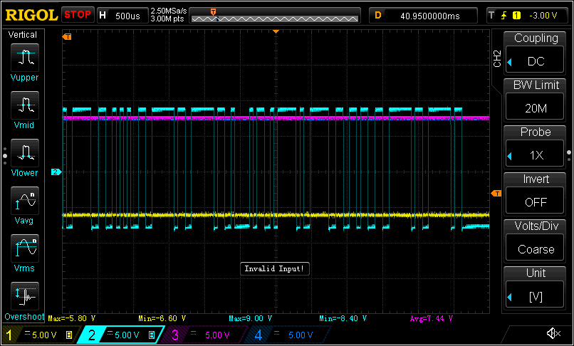
If I disconnect the DMM from the RTS line, everything seems to work fine. The DMM drives the RxD line to -9v at idle, and sustains signal quality throughout a transmission.
 I can’t imagine I’m the first person to come across this. I’m surprised though that I can’t find any mention of it online.
Update:
I posted about this in the EEVBlog Forums and a few users provided some details of similar issues they’ve had with RS-232 communications on the Keithley 2000 DMM. None of them have gone as deep as I have, but their descriptions are explained by my hypothesis.
I’m interested in whether later versions of the firmware leave the RST pin floating. So far no one with more recent firmware has checked for me, but one user remembers someone getting a similar problem fixed with a firmware update.
I’ll probably try doing a firmware update on my own. One user reports that he figured out he could use some Flash chips replace the EPROMs, which is attractive because I can re-use the chips and I don’t have to buy a legacy device like an EPROM programmer.
In the meantime, I picked up a straight-through male-to-female DB-9 cable and clipped off the RTS pin (#7). With it in place between the USB RS-232 adapter and the DMM, I ran a test querying the DMM with “*IDN?” every second for an hour or so. The DMM remained responsive for the whole time, and the responses it sent were complete, and uncorrupted. Previously things crapped out within a few minutes and only a few commands.
Update 2015-07-20:
I now have a unit from ~2007. It leaves the level of the RTS pin to the DTE, as it should. Upon closer inspection I found that the board has been revised so the RTS pin is no longer connected to the level shifter IC at all.