I noticed that Banggood just listed the H&V HV-50 TDA 7492 Class-D amp on their site for $59.99 with “Priority Direct” shipping to the US from China. This reminded me that I’ve been remiss in posting anything more about the HV-50 amp I ordered on eBay last summer for ~$35.
After ordering it, I was a bit worried I’d been scammed, because the seller never provided any tracking information, but those fears were quickly laid to rest when it arrived on my doorstep all the way from China in just 9 days!
Sheeny
Some details from my earlier post on the HV-50:
- 50W per channel (stereo)
- RCA inputs
- 5-way binding posts for outputs.
- Based on the TDA7492 Class D Amplifier IC from ST Microelectronics.
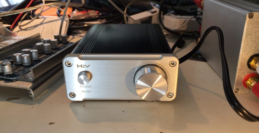
- Aluminum case.
The TDA7492 chip is used in a lot of compact, inexpensive audio amps made by various Chinese manufacturers and sold under various names on Amazon, Ebay, AliExpress, etc.
One such amp is/was the very similar looking SMSL SA-50 amplifier, which puzzled me, because when I first found the HV-50 listed on AliExpress, the seller listed it as an SMSL product. It wasn’t until I had it in hand that I realized that the eBay listing didn’t mention SMSL and there was actually no reference to SMSL anywhere on the product, or or the very thin users manual.
With some digging though, I found persuasive evidence that H&V is/was a new brand from he same company that produced SMSL. Given the price point, and product photos of the HV-50s internals, which showed signs of cost cutting, I assumed the H&V line would be a new, lower cost line, as SMSL seemed to be moving upmarket. Positioning the HV-50 as a lower cost alternative to SA-50 or A2 amps made sense when the HV-50 sold for $35-40, while the SA-50 & A2 were selling for roughly twice that. It makes less sense with the HV-50 selling for almost $60.
Looking more closely, the SA-50 seems unavailable from Chinese sellers on AliExpress and eBay these days. On Amazon, it sill goes for $60-70. The HV-50 seems to be in the process of being superseded. Aoshida, the source of my original amp seems to have both an eBay and and AliExpress presence. On AliExpress, they have a listing that pictures an HV-50 with a 24v power adapter for $42.28, shipped, but the listing is actually for a “TOE F1 TDA7492 amp” and notes that the housing may say HV-50, but it’s been “upgraded to TOE F1.” Their eBay store has a very similar listing, also for a “TOE F1 TDA7492 amp” for $53.00.
I think the HV-50/TOE F1 is a pretty good deal at $42 shipped with a power brick. At $50-60, that’s less clear. I’d probably pay another $10-15 for an SMSL SA-50. The reason? If the SA-50s shipping today are the same as those shipping a year ago (not a sure thing, given that SMSL changed the guts on the SA-36pro without warning, explanation, or acknowledgement) then they use some high quality film capacitors in key parts of the audio path.
On the other hand, the HV is clearly a cost reduced design, as I suspected from the initial product photos, and confirmed upon receipt. It uses SMD ceramic caps for all but the main power supply caps. I personally think the cheaper caps work well enough. I don’t have an SA-50 to compare the HV-50 to, but while it’s possible they would sound obviously different, I doubt the SA-50 sounds noticeably better. For $30 less than the SA-50, I think the HV-50 is an obvious choice for those on a budget. For the current $10-15, price difference, it is much less clear cut.
What remains to be seen is if the TOE F1 is actually an upgrade, and if so, in what way? Will they adopt the film caps used by the SA-50?
Impressions
When powered up, a tiny click may be emitted from the connected speakers.
I noticed no obvious defects in sound quality. My main complaint is that the design & construction of the PCB-mounted RCA inputs doesn’t make good solid contact with the slotted, machined pins on some higher-quality RCA plugs, leading to noise or audo drop-outs. At first, I though the volume control pot was going bad. I ended up replacing the jacks with some gold-plated panel mount jacks with better design/construction. Interestingly enough, while the original part has trouble with higher-end RCA plugs, it has no problem at all with inexpensive stamped & rolled RCA plugs.
Speaking of connections, the speaker output binding posts are small, but work well with banana plugs, spade connectors and properly trimmed and stripped speaker wire (to avoid shorts).
Caveats
There are a few important caveats about the HV-50, which may or may not apply to the TOE F1:
First, it’s important to understand that the generation of class D amplifier chips like the TDA7492 used in the HV-50, along with the more powerful TDA7498, and the comprable TPA3116, all have consistently inflated power ratings. These ratings are often used in the specs of cheap amps built around such chips.
The inflated ratings aren’t exactly inaccurate, its just that they only apply under unlikely listening conditions. They assume a power supply voltage near the top of their operating range which ends up being 24v for the TDA7492 and TPA3116. This isn’t an issue with the HV-50, which comes with a 24v supply, but can come into play when using ~19-20v laptop adapters. The tests are often performed with ~4 Ohm loads, while lots of home audio speakers are closer to 8 Ohm, and peak power output would be ~50% of the advertised number. The finally issue with the ratings is that they allow up to 10% distortion, a value that most people will find unlistenable. Values are generally also given for up to 1% distortion, which most people will find suitable. The corresponding power ratings are ~50-60% of the advertised value.
In sum then, the usable power of the HV-50 and similar amps with a suitable power supply is 50W * 50% (for 8Ohm speakers) * 60% (for reasonable distortion levels), which works out to 15w/channel. This may seem much less impressive, but it should be enough power to push most consumer bookshelf speakers close to their (and your) limits.
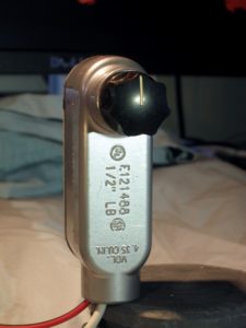
Second, the HV-50 does not, as claimed in the Bangood listing and elsewhere, contain parts from EPCOS, Philips, ALPS, DALE, etc. The volume control pot seems like a cheap, but adequate generic Chinese part, and the capacitors in the audio path are all SMD ceramics.
Conclusion
Bottom line: The HV-50 is a decent, inexpensive Class D amp if you can get it shipped with PSU for ~$40. Whether it is a good choice vs an SA-50 or similar really depends on the price difference at current market prices.
Photos
And finally, the main purpose of this post wasn’t writing a wall of text, it was sharing photos of the guts of my HV-50.
-
-
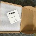
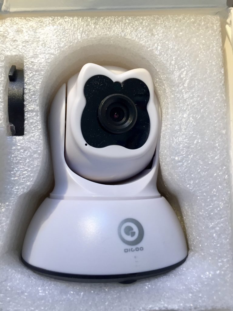
Minimal but sufficient packaging
-
-
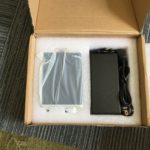
HV-50 Unboxing
-
-
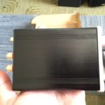
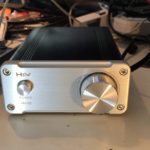
A nice, small, solid, aluminum case.
-
-
Sheeny
-
-
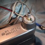
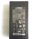
Genuine LiteOn 24V PSU?
-
-
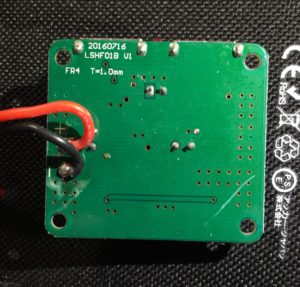
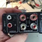
Rear panel
-
-
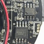
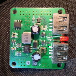
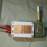
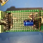
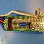
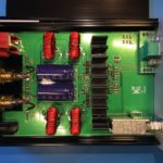
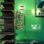
Top of PCB
-
-
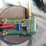
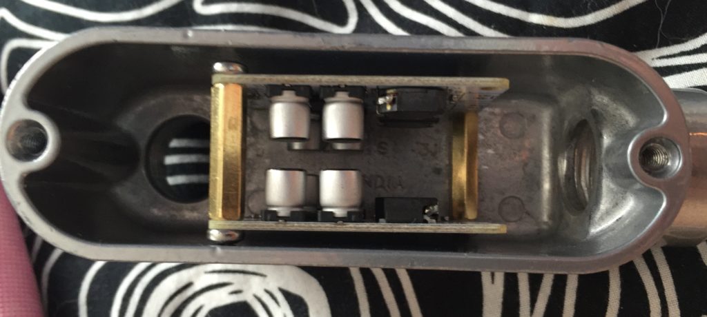
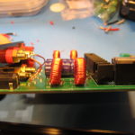
SMD input caps.
-
-
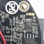
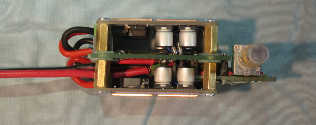
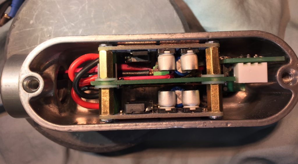
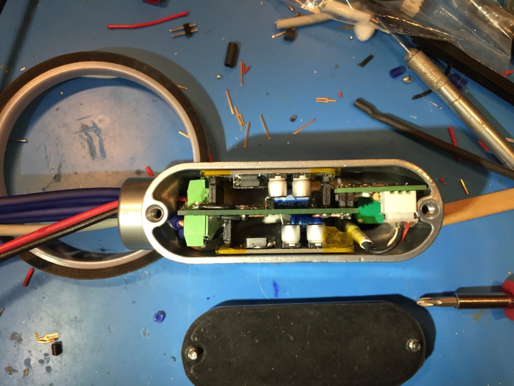
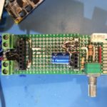
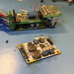
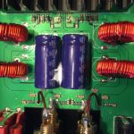
Output filters and power supply caps
-
-
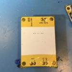
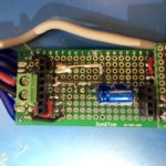
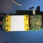
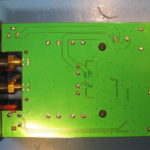
Back of PCB
-
-
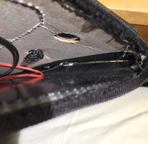
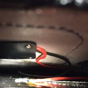
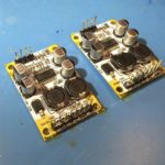
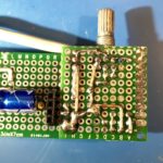
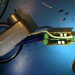
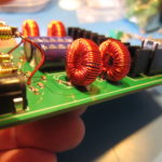
Detail of odd inductor soldering.
-
-
Inductors aren’t well supported.
 I gave up on the quest, but here are my notes, with minimal editing.