Info on hacking a kankun Atheros-based wifi socket running OpenWRT
Source: kankun – How to Linux
Info on hacking a kankun Atheros-based wifi socket running OpenWRT
Source: kankun – How to Linux
More info on local control of Orvibo S20 Socket
Source: Orvibo S20 WiFi Mains Socket with Node-RED – nathan.chantrell.net
Good info on hacking/spoofing the Orvibo S20 WiFi socket. Unfortunately, it appears that the security of the cloud service is (was?) really bad.
Source: Reverse engineering Orvibo S20 socket « Andrius Štikonas
Code to allow OTA installation of alternative firmware on Sonoff devices, avoiding the need to connect to the serial port.
Source: mirko/SonOTA: Flashing Itead Sonoff devices with custom firmware via original OTA mechanism
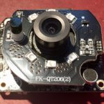
I was just looking at unfinished posts and noticed that I’d taken, but not published, a bunch of notes I’d made earlier this year in hopes of hacking better firmware onto the Digoo BB-M2 WiFi PTZ Security Camera.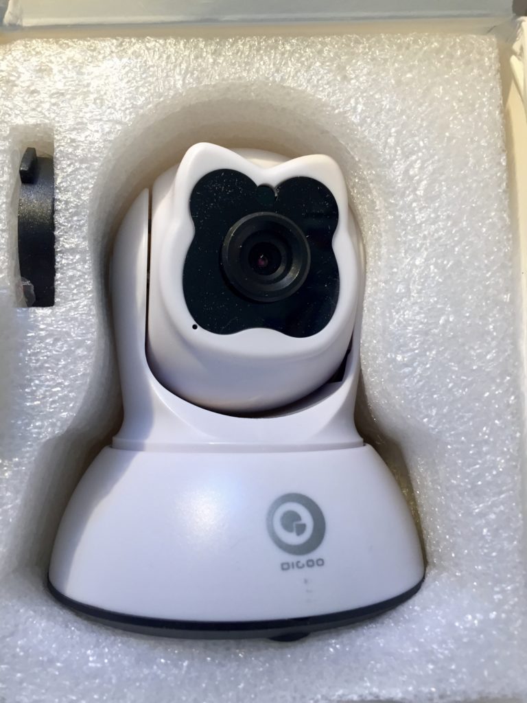 I gave up on the quest, but here are my notes, with minimal editing.
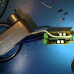
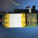
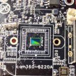
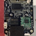
Someone mentioned that the Chinese language page for Netcam360 has a link to the IPC-SDK. When I downloaded it and looked inside, I saw client-side code, but there was also a self-extracting archive called “HSmartLink Win32 SDK” and I remembered the PCB marking started with “HSL.” Searching for HSmartLink brings up hsmartlink.com, which, among other things, has IP webcams! The i9812 looks like a good match for my camera!
Unfortunately, no sign of any firmware updates. I checked the .cn version of the site too. It doesn’t seem as up to date on products (i9812 isn’t listed), and while there is more info in support section, it is still quite sparse. Page that looks like it is intended to link to downloads hasn’t been updated since 2015
Company is “Shenzhen Hsmartlink Technology Co. Ltd”
FCC Database listing for company
So what is the relationship to NetCam360 (check whois & IP ) and they mysterious APKLink?
Starting Nmap 7.40 ( https://nmap.org ) at 2017-02-06 18:38 PST
Nmap scan report for 10.31.1.124
Host is up (0.0043s latency).
Not shown: 998 closed ports
PORT STATE SERVICE
23/tcp open telnet
81/tcp open hosts2-ns
MAC Address: E0:B9:4D:8F:61:6C (Shenzhen Bilian Electronicltd)

Nmap done: 1 IP address (1 host up) scanned in 0.49 seconds
I picked up a 21W, 3-panel Balight folding solar panel-based USB charger from Amazon for ~$36 a couple of weeks back. It uses high-efficiency SunPower Maxeon cells much like similar 20-21W panels from Aukey, Anker and dozens of obscure brands. All of them have the same basic construction. They are all made from nylon ballistic cloth. Each fold has a panel made from two SunPower cells encapsulated in a flexible waterpoof sheet. The panels provide power via two 5v USB ports, which presumably have some sort of voltage regulator.
I wanted to know more about how the chargers worked. In particular, I wanted to know if they were wired in series, or parallel because I wondered if it was worth trying to tap into the raw output, before the USB regulator to reduce power conversion and resistive losses for some applications.
I thought I’d be able to get the information I needed by finding someone documenting a teardown of their own panel on YouTube or a blog post. Despite the dozens of variants from dozens of brands and a handful of manufactures though, I didn’t find what I was looking for.
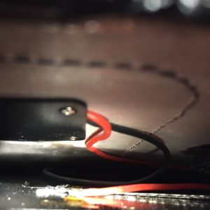
So, I decided to dig up a seam ripper and open my panel far enough to get a look at the wiring, and tap in to it upstream of the voltage regulator.
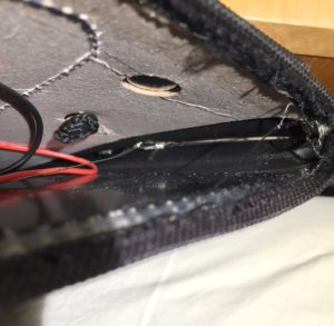
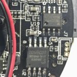
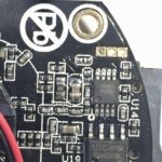
The panels appear to be wired together with some sort of woven wire conductor. I had some hope that all the cells would be wired in series, to give a nominal panel voltage of 18v. Based on what I could see, and measuring the voltage before the regulator in full sun, it looks like each panel is wired in series, for 6v nominal voltage, and then the panels are wired together in parallel. I was disappointed at first, but this arrangement makes sense in upon further thought.
Using a 2s3p configuration means that the input voltage into the switching regulator should be pretty close to the 5v (actually, 5.2v with enough sun and a light enough load) output of the USB power regulator, which will typically have higher conversion efficiency than 12 or 18 volts. It also means that the manufacturers can stock one converter for everything from a 7W single-panel charger, up to a 28w 4 panel charger without the converter having to support a wide range of input voltages. Perhaps most importantly, it means that partial shading of one panel shouldn’t have a disproportionate impact on the power output of the entire array.
The only downside is that resistive losses in the cabling will be higher with lower voltage and higher current, but that the interconnects aren’t more than a foot or so, the resistive losses shouldn’t be too high.
As for the converter itself, I may look at it more closely and add some more details, but, a few initial observations:
There you go. I can’t be sure that other folding solar arrays like this one are wired in the same way, but if they only support a 5v output, I suspect they will be. I hope this proves useful to someone besides me.
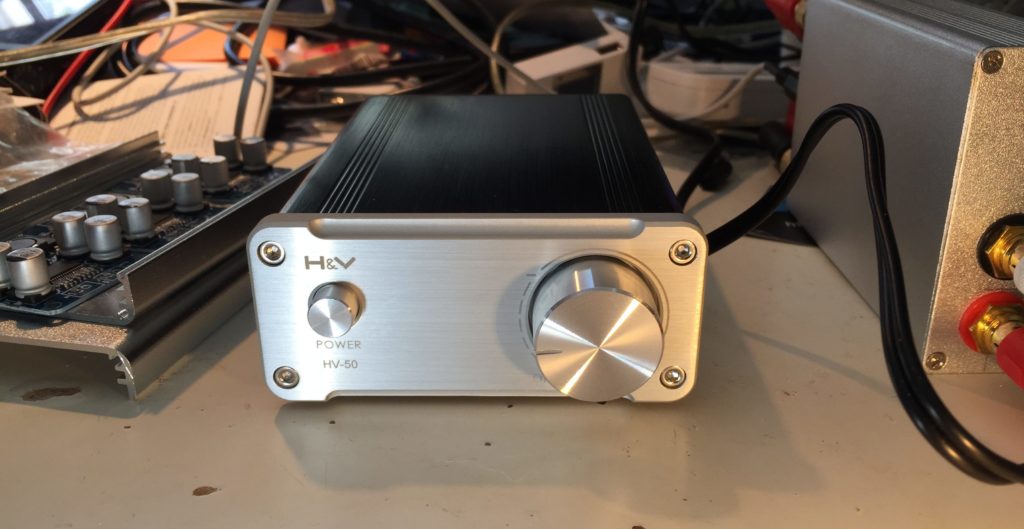
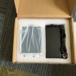
I noticed that Banggood just listed the H&V HV-50 TDA 7492 Class-D amp on their site for $59.99 with “Priority Direct” shipping to the US from China. This reminded me that I’ve been remiss in posting anything more about the HV-50 amp I ordered on eBay last summer for ~$35.
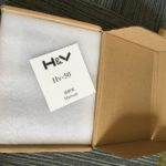
After ordering it, I was a bit worried I’d been scammed, because the seller never provided any tracking information, but those fears were quickly laid to rest when it arrived on my doorstep all the way from China in just 9 days!
Sheeny
Some details from my earlier post on the HV-50:
The TDA7492 chip is used in a lot of compact, inexpensive audio amps made by various Chinese manufacturers and sold under various names on Amazon, Ebay, AliExpress, etc.
One such amp is/was the very similar looking SMSL SA-50 amplifier, which puzzled me, because when I first found the HV-50 listed on AliExpress, the seller listed it as an SMSL product. It wasn’t until I had it in hand that I realized that the eBay listing didn’t mention SMSL and there was actually no reference to SMSL anywhere on the product, or or the very thin users manual.
With some digging though, I found persuasive evidence that H&V is/was a new brand from he same company that produced SMSL. Given the price point, and product photos of the HV-50s internals, which showed signs of cost cutting, I assumed the H&V line would be a new, lower cost line, as SMSL seemed to be moving upmarket. Positioning the HV-50 as a lower cost alternative to SA-50 or A2 amps made sense when the HV-50 sold for $35-40, while the SA-50 & A2 were selling for roughly twice that. It makes less sense with the HV-50 selling for almost $60.
Looking more closely, the SA-50 seems unavailable from Chinese sellers on AliExpress and eBay these days. On Amazon, it sill goes for $60-70. The HV-50 seems to be in the process of being superseded. Aoshida, the source of my original amp seems to have both an eBay and and AliExpress presence. On AliExpress, they have a listing that pictures an HV-50 with a 24v power adapter for $42.28, shipped, but the listing is actually for a “TOE F1 TDA7492 amp” and notes that the housing may say HV-50, but it’s been “upgraded to TOE F1.” Their eBay store has a very similar listing, also for a “TOE F1 TDA7492 amp” for $53.00.
I think the HV-50/TOE F1 is a pretty good deal at $42 shipped with a power brick. At $50-60, that’s less clear. I’d probably pay another $10-15 for an SMSL SA-50. The reason? If the SA-50s shipping today are the same as those shipping a year ago (not a sure thing, given that SMSL changed the guts on the SA-36pro without warning, explanation, or acknowledgement) then they use some high quality film capacitors in key parts of the audio path.
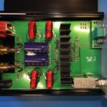
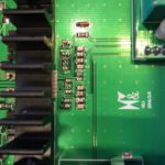
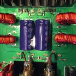
On the other hand, the HV is clearly a cost reduced design, as I suspected from the initial product photos, and confirmed upon receipt. It uses SMD ceramic caps for all but the main power supply caps. I personally think the cheaper caps work well enough. I don’t have an SA-50 to compare the HV-50 to, but while it’s possible they would sound obviously different, I doubt the SA-50 sounds noticeably better. For $30 less than the SA-50, I think the HV-50 is an obvious choice for those on a budget. For the current $10-15, price difference, it is much less clear cut.
What remains to be seen is if the TOE F1 is actually an upgrade, and if so, in what way? Will they adopt the film caps used by the SA-50?
When powered up, a tiny click may be emitted from the connected speakers.
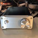
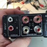
I noticed no obvious defects in sound quality. My main complaint is that the design & construction of the PCB-mounted RCA inputs doesn’t make good solid contact with the slotted, machined pins on some higher-quality RCA plugs, leading to noise or audo drop-outs. At first, I though the volume control pot was going bad. I ended up replacing the jacks with some gold-plated panel mount jacks with better design/construction. Interestingly enough, while the original part has trouble with higher-end RCA plugs, it has no problem at all with inexpensive stamped & rolled RCA plugs.
Speaking of connections, the speaker output binding posts are small, but work well with banana plugs, spade connectors and properly trimmed and stripped speaker wire (to avoid shorts).
There are a few important caveats about the HV-50, which may or may not apply to the TOE F1:
First, it’s important to understand that the generation of class D amplifier chips like the TDA7492 used in the HV-50, along with the more powerful TDA7498, and the comprable TPA3116, all have consistently inflated power ratings. These ratings are often used in the specs of cheap amps built around such chips.
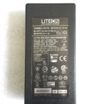
The inflated ratings aren’t exactly inaccurate, its just that they only apply under unlikely listening conditions. They assume a power supply voltage near the top of their operating range which ends up being 24v for the TDA7492 and TPA3116. This isn’t an issue with the HV-50, which comes with a 24v supply, but can come into play when using ~19-20v laptop adapters. The tests are often performed with ~4 Ohm loads, while lots of home audio speakers are closer to 8 Ohm, and peak power output would be ~50% of the advertised number. The finally issue with the ratings is that they allow up to 10% distortion, a value that most people will find unlistenable. Values are generally also given for up to 1% distortion, which most people will find suitable. The corresponding power ratings are ~50-60% of the advertised value.
In sum then, the usable power of the HV-50 and similar amps with a suitable power supply is 50W * 50% (for 8Ohm speakers) * 60% (for reasonable distortion levels), which works out to 15w/channel. This may seem much less impressive, but it should be enough power to push most consumer bookshelf speakers close to their (and your) limits.
Second, the HV-50 does not, as claimed in the Bangood listing and elsewhere, contain parts from EPCOS, Philips, ALPS, DALE, etc. The volume control pot seems like a cheap, but adequate generic Chinese part, and the capacitors in the audio path are all SMD ceramics.
Bottom line: The HV-50 is a decent, inexpensive Class D amp if you can get it shipped with PSU for ~$40. Whether it is a good choice vs an SA-50 or similar really depends on the price difference at current market prices.
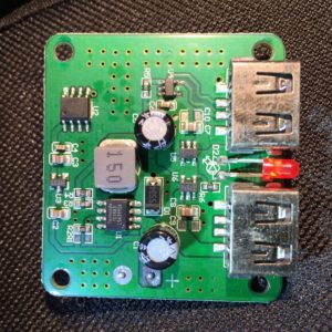
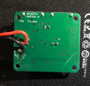
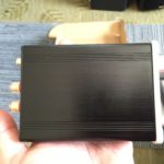
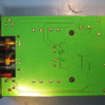
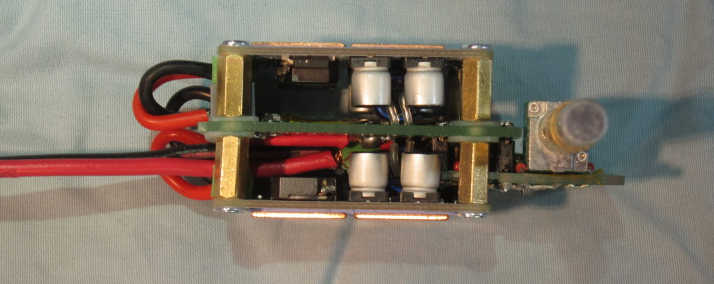
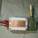
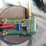
And finally, the main purpose of this post wasn’t writing a wall of text, it was sharing photos of the guts of my HV-50.
Sweet new project!
ESP8266-HomeKit – HomeKit server on ESP8266 RTOS with an API approach
Source: HomeACcessoryKid/ESP8266-HomeKit: HomeKit server on ESP8266 RTOS with an API approach
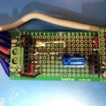
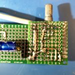
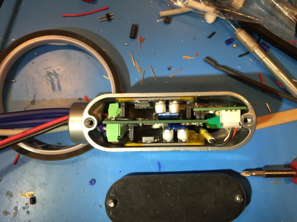
I made a major revision to my Conduit amp in order to free some internal space to ease cabling.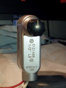
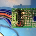
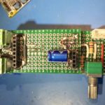
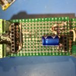
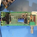
The original version used pin-headers on the mono TPA3110 amplifier modules to connect them to a perfboard motherboard. Connectors for power input and speaker output terminals were on the motherbnoard. The new version uses smaller screw terminals, and moves the speaker output terminals to the amp modules, which are held in place by sandoffs. Pin headers are still used for audio inputs to the modules, and power is still connected to the motherboard, and then supplied to screw terminals on the modules via 18 gauge silicone wire. I also managed a more compact layout for the volume control daughter board.
The new version also included improved fit-and-finish to the volume control. I used some aluminum rod and brass tubing to make an extension. This now passes through a drilled-out aluminum plug before being connected to the knob. I’d originally intended to fit a bearing in the plug to support the shaft, but I don’t have one in the proper size (even so, after adjustment shaft alignment is better than pictured).
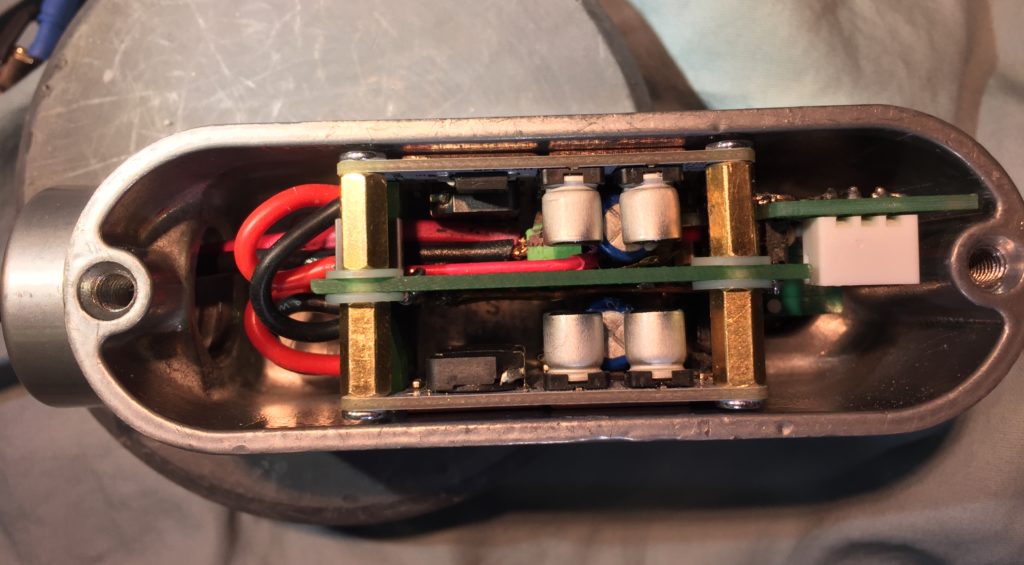
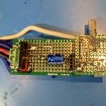
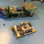
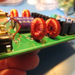
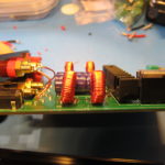
I also fitted the thermal pad and copper shims to thermally couple the amp modules to the aluminum case.
Unfortunately, only one channel works. I checked for continuity and power before noticing that a small SMD cap near the PTA3110 chip on the amp board got knocked loose. I’ll have to figure out its specs and try to get and fit a replacement… though it would be easier to just replace the board for $2.50.
I think its a nice improvement. I still need to get wire and connectors I’m happy with the power, speaker, and audio pigtails. Someone suggested 4-pole speakon connectors for the speakers. There is an aluminum version that might be a good match for the case, except it costs about as much as all the other parts combined. There are cheaper plastic speakon connectors that I might try. I’d also like to find a decent pot with an integrated switch I can use to switch the power.
Update: I made a major revision to The Conduit Amp with some improvements and a bit better fit and finish.
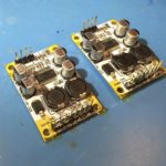
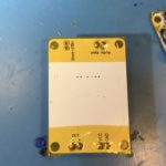
A few months ago I was at the hardware store looking for cheap enclosures for electronics projects. Some aluminum junction boxes for electrical conduit caught my eye, so I bought a couple. In parallel, I was interested in building a small, portable amp that could operate off 12v, which led me to buy some little, mono, TPA3110 modules for a few bucks each.
Surveying my box of parts a couple weeks ago, I noticed that the TPA3110 modules would fit nicely in the smaller of the two junction boxes I purchased, and I started tinkering with ways to assemble them into a finished product.
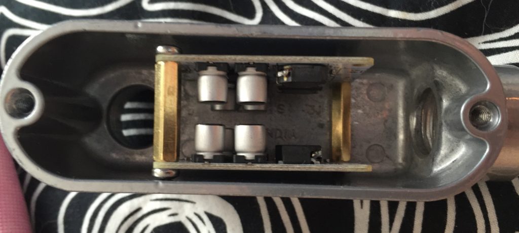
The first idea was to join the boards together with standoffs and slip them inside. I ordered some small terminal blocks for the electrical connections. When they came, though, and I tried assembling things as I planned, I realized I’d need to cut the standoffs down in order to fit a board to hold a potentiometer. I was feeling lazy, and didn’t want to deal with metal filings, so I looked for another way.
I decided to use pin-headers to mate the amp modules with small motherboard made from perfboard. For added mechanical strength, I cut the headers with more pins than needed, soldered the pin positions with through-holes on the amp board, and then glued the rest and trimmed them to the same length as the active pins.
Routing the power input and speaker outputs was kind of a nightmare. Rather than trying to plan it all out, I ended up working a couple of connections at once, trying to leave room for the other connections. It took quite a while. I was concerned about some of the routing and figured I’d probably end up doing a second version, so I soldiered on soldering my prototype.
Once I was done, I used my multimeter to check to make sure that there weren’t any short circuits on the motherboard. Fortunately, everything checked out.
Next I had to finish up the input connections and passive volume control. Rather than routing the audio input on the protoboard, I decided to take advantage of the shielding on the input to help keep the signal clean while passing the high-current power and output connections, and the inductors on the amp board. I connected it to the board with the volume-control board at the far end of the case.
After assembling the components on the volume control board I checked everything with a multimeter. Again, I was fortunate that I hadn’t ended up with any shorts. The volume control board was connected to the the “motherboard” with an excess of soldered pin headers for mechanical stability.
I covered the solder pads on the backs of the amp boards with kapton tape to keep them from shorting on the case. Then I made up a power cable and some speaker cables, screwed them in to the terminals on the motherboard and fed them out of the opening of the case.
Maneuvering the amp board into the case with all the cables attached took a bit more force than I was hoping for, a situation not helped by the fact that the position I chose for for the audio input connector interfered with part of the case casting, depriving me of a few extra mm at the opposite side of the case, and putting the volume-pot a bit off center.
In the end though, I got it to fit.
My plan is to power it off a Quick Charge 2 USB power bank set for 12v output. I have the powerbank, but I still need to make something to negotiate the 12v output, so I powered it off a 12v power brick to test it out.
It works! Even better, it sounds good! So, a second version is a luxury, rather than a necessity. At full volume, the output level with my phone as the audio source is maybe a little lower than I’d like for something intended for use outdoors. I’m not sure yet if that’s a limitation of the 12v supply voltage, or if I need to bump up the gain of the amplifier.
Now that I know it works, I still need to finish it up. I need to fit an extension to the volume potentiometer shaft and pick out a knob that looks good. I also need to put some thermal pads on the bottom of the amp modules to transfer heat to the case. Also I’ll probably find some thinner gauge speaker cable.